Graphite composite sealing gasket processing system

A composite sealing and processing system technology, which is applied in the field of graphite composite sealing gasket processing and processing systems, can solve the problems of poor control of precision, low efficiency, labor consumption, etc., so as to avoid manual feeding , improve efficiency and accuracy, and reduce the effect of human labor

Active Publication Date: 2020-12-01
佛山市锐昂科技有限公司
View PDF5 Cites 0 Cited by
  • Summary
  • Abstract
  • Description
  • Claims
  • Application Information

AI Technical Summary

Problems solved by technology

[0003] The existing graphite rods are usually propelled by manually moving the graphite rods during the processing process, using a cutter to cut the graphite rods, and then transporting them to the stamping area and using a ring cutter to cut the graphite rods. Stamping processing produces the required graphite gaskets, but this method has the following problems: a. Controlling the advancement of graphite rods by manual advancement On the one hand, the accuracy cannot be well controlled, even if some distance-limiting structures can be used to assist manual propulsion, but on the other hand, this method has the disadvantages of low efficiency, and consumes manual labor; b. The graphite slices cut by the cutter are usually piled up in disorder and collected in a container at one end, which cannot be used for cutting. The graphite slices that come down are collected in a centralized, uniform and orderly manner, and then manually transported to the stamping area for processing, which increases the labor force in the above process, and needs to rearrange the graphite slices and put them into the stamping area for processing, which leads to The entire graphite gasket process from slicing to stamping cannot be carried out smoothly and orderly, requiring a lot of manual labor, which is time-consuming and labor-intensive

Method used


Image

  • Graphite composite sealing gasket processing system
  • Graphite composite sealing gasket processing system
  • Graphite composite sealing gasket processing system

Examples


Embodiment Construction

[0026] The embodiments of the present invention will be described in detail below with reference to the accompanying drawings, but the present invention can be implemented in many different ways defined and covered by the claims.

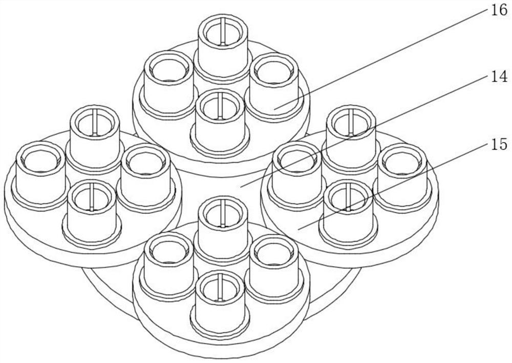
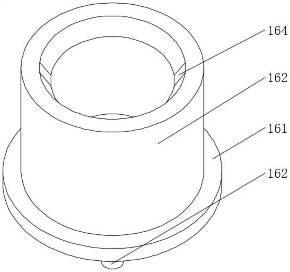
[0027] Such as Figure 1 to Figure 8 As shown, a graphite composite sealing gasket processing system includes a collection device 1, a cutting device 2, a feeding device 3 and a vertical plate 4, the bottom end of the collection device 1 is fixedly connected to the ground through a support column, and the cutting device 2 comes out The material end is located directly above the corresponding position of one end of the collecting device 1, the cutting device 2 is fixedly installed on one end of the vertical plate 4, the bottom end of the vertical plate 4 is fixedly installed on the ground, and the top end of the cutting device 2 is fixedly installed with a feeding device 3;

[0028] The collection device 1 includes a driving motor 11 fixedly installe...


PUM


Abstract

The invention relates to a graphite composite sealing gasket processing system. The system comprises a collecting device, a cutting device, a feeding device and a vertical plate. The bottom end of thecollecting device is fixedly connected to the ground through a supporting column. The discharging end of the cutting device is located over the corresponding position of one end of the collecting device. The cutting device is fixedly installed at one end of the vertical plate. The bottom end of the vertical plate is fixedly installed on the ground. The feeding device is fixedly installed at the top end of the cutting device. According to the graphite composite sealing gasket processing system, a cutter can be driven through the rotation of fourth gears, the cutter rotates to drive threaded rods to rotate, and therefore the purpose that two clamps in the whole feeding device grab graphite rods in turn to push the graphite rods downwards under the action of rotation of the fourth gears is achieved through the threaded rods, automatic feeding of the graphite rods is achieved, manual feeding is omitted, the labor force is liberated, and the efficiency and the accuracy are also improved.

Description

technical field [0001] The invention relates to the technical field of graphite gasket processing equipment, in particular to a graphite composite sealing gasket processing system. Background technique [0002] Graphite gaskets are cut and stamped from pure graphite rods or metal-reinforced graphite rods. Due to their thermal stability, self-lubrication, corrosion resistance, no aging, no brittleness, and long-term stable use under harsh working conditions, they are extremely It is widely used in pipelines, valves, pumps, pressure vessels, heat exchangers, condensers, generators and other fields due to its excellent sealing properties such as less maintenance. [0003] The existing graphite rods are usually propelled by manually moving the graphite rods during the processing process, using a cutter to cut the graphite rods, and then transporting them to the stamping area and using a ring cutter to cut the graphite rods. Stamping processing produces the required graphite gas...

Claims


Application Information

Patent Timeline
Patent Type & Authority Applications(China)
IPC IPC(8): B28D1/26B28D1/00B28D1/22B28D7/00B28D7/04
CPCB28D1/003B28D1/22B28D1/26B28D7/00B28D7/04
Inventor 倪立秧
Owner 佛山市锐昂科技有限公司
Why Eureka
Try Eureka