Solder tip resistant to oxidation and corrosion under high temperature and production method of solder tip

A production method and oxidation-resistant technology, which is applied to soldering irons, manufacturing tools, soldering positions, etc., can solve problems such as soldering iron tip oxidation, perforation, and poor thermal conductivity of the soldering iron tip, and achieve improved oxidation resistance, longer service life, and rapid heat conduction Effect

Inactive Publication Date: 2020-11-24
深圳市纳泽科技有限公司
View PDF5 Cites 0 Cited by
  • Summary
  • Abstract
  • Description
  • Claims
  • Application Information

AI Technical Summary

Problems solved by technology

The traditional method of producing soldering iron tips in the industry is that copper rods are machined into copper billets, and then processed into copper substrates, and then undergo a series of electroplating treatments such as iron plating, nickel plating, and chrome plating, and finally make soldering iron tips. Among them, The ratio and thickness of the gold-plated layer will directly affect the quality of the soldering iron tip. If the thickness of the gold-plated layer is not well done, it will cause poor thermal conductivity of the soldering iron tip, poor soldering, and sharp edges, which will lead to false soldering and false soldering. Poor solder joints; if the ratio of the gold-plated layer is not good, it will cause the tip of the soldering iron to oxidize, corrode, and even be scrapped due to perforation and tip breakage during high-temperature work
This production process not only increases the production cost, but at the same time, frequent replacement of soldering iron tips reduces work efficiency, which has become a recognized problem in the industry.

Method used


Image

  • Solder tip resistant to oxidation and corrosion under high temperature and production method of solder tip
  • Solder tip resistant to oxidation and corrosion under high temperature and production method of solder tip
  • Solder tip resistant to oxidation and corrosion under high temperature and production method of solder tip

Examples


Embodiment Construction

[0020] The specific embodiments of the present invention will be further described below in conjunction with the accompanying drawings. It should be noted here that the descriptions of these embodiments are used to help understand the present invention, but are not intended to limit the present invention. In addition, the technical features involved in the various embodiments of the present invention described below may be combined with each other as long as they do not constitute a conflict with each other.

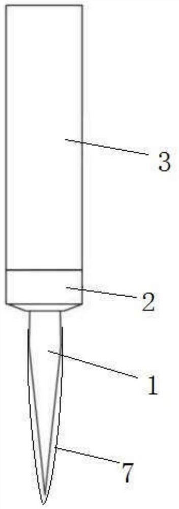
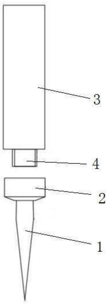
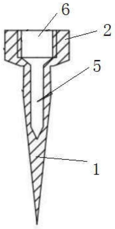
[0021] according to figure 1 , 2 As shown, this embodiment proposes a soldering iron tip that is resistant to oxidation and corrosion at high temperatures and a manufacturing method thereof, including a soldering tip and a mounting tube 3, one end of the mounting tube 3 is detachably connected to the soldering tip, and the other end is connected to an external electric soldering iron. The soldering iron core is connected, and the welding head includes a mounting base 2...


PUM


Abstract

The invention discloses a solder tip resistant to oxidation and corrosion under high temperature and a production method of the solder tip. The solder tip comprises a welding head and a mounting pipe,wherein one end of the mounting pipe is detachably connected with the welding head, the other end of the mounting pipe is connected with a soldering iron core of an external electric soldering iron,the welding head comprises a mounting base and a heating portion arranged on the mounting base, the heating portion is plated with an anti-oxidation layer, the welding head is made of an alloy consisting of nickel, chromium and aluminum, and then the welding head is sequentially placed into electroplating nickel liquid, electroplating aluminum liquid and electroplating chromium liquid at preset temperature, so that the plating work on the anti-oxidation layer is completed. The solder tip has the advantages that the oxidation resistance and corrosion resistance of the produced solder tip are greatly improved under the high temperature, the solder tip is not prone to oxidation, corrosion or perforation, the anti-oxidation layer well protects the solder tip, and the service life is prolongedfor a long time.

Description

technical field [0001] The invention relates to the technical field of soldering iron tip production, in particular to an oxidation-resistant and corrosion-resistant soldering iron tip at high temperature and a manufacturing method thereof. Background technique [0002] The soldering iron tip is the key component of the electric soldering iron or soldering station, and it is an important part that affects the soldering effect and service life. During the soldering operation, the soldering iron tip is in direct contact with the tin material and is always in a high temperature state of 360-420 degrees. At present, the industry generally implements the EU ROHS directive. After the introduction of lead-free solder, the working temperature is as high as 420-480 degrees. Therefore, higher requirements are put forward for the high temperature resistance, oxidation resistance and corrosion resistance of the soldering iron tip. The traditional method of producing soldering iron tips ...

Claims


Application Information

Patent Timeline
Patent Type & Authority Applications(China)
IPC IPC(8): B23K3/02C25D3/04C25D3/12C25D3/44C25D5/14
CPCB23K3/025C25D3/04C25D3/12C25D3/44C25D5/14
Inventor 陈先洪
Owner 深圳市纳泽科技有限公司
Why Eureka
Try Eureka