Eureka AIR delivers breakthrough ideas for toughest innovation challenges, trusted by R&D personnel around the world.

Polishing head and wafer polishing method

A grinding head and wafer technology, which is applied to grinding/polishing equipment, electrical components, work carriers, etc., can solve the problems of increased machining allowance displacement, deterioration of grinding uniformity, and inability to uniformly grind wafers, etc. Achieve the effect of uniform machining allowance and reducing local deformation

Pending Publication Date: 2020-11-20
SHIN-ETSU HANDOTAI CO LTD
View PDF14 Cites 0 Cited by
  • Summary
  • Abstract
  • Description
  • Claims
  • Application Information

AI Technical Summary

Problems solved by technology

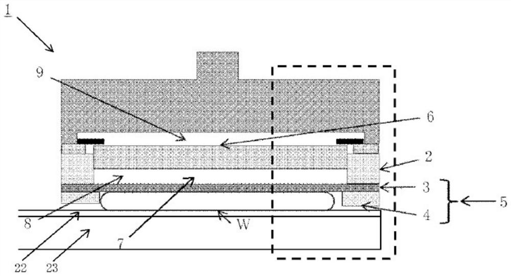
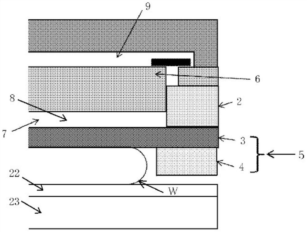
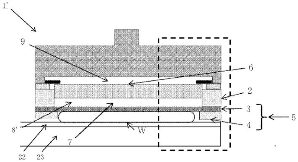
It can be seen that in the conventional polishing head 1', in order to make the load applied to the wafer uniform, water 8', which is one of the incompressible fluids, is sealed to reduce the fine gap formed between the template 5 and the wafer W. part of the gasket deformed, but as Figure 4 As shown, the pad 3 is locally deformed at the outermost peripheral portion of the wafer W, resulting in deterioration of the polishing uniformity at the outermost peripheral portion of the wafer W.
[0008] That is to say, when using the existing grinding head for grinding processing, such as Image 6 As shown, the machining allowance displacement increases at the outermost periphery of the wafer (from 149mm to 147mm from the wafer position), making it impossible to grind the wafer uniformly

Method used


Image

  • Polishing head and wafer polishing method
  • Polishing head and wafer polishing method
  • Polishing head and wafer polishing method

Examples


Embodiment 1-3

[0064] The change in viscosity with respect to the PVA concentration was confirmed, and the PVA concentration of the fluid enclosed in the polishing head was set to 6w% (10mPa·s) (Example 1), 12w% (90mPa·s) (Example 2) and 20w% ( 1200mPa·s) (Example 3) three levels.

[0065] In addition, three levels of incompressible fluids were sealed into the polishing head at the same pressure (approximately 15 kPa) to perform wafer polishing processing, and the difference in machining allowance profile before and after processing was compared.

[0066] As mentioned above, use Picture 12 The fluid sealing devices shown in (A) and (B) are filled with incompressible fluid. At this time, when the thickness of the template is 700 μm (when using a guide ring thinner than the thickness of the wafer), insert a 75 μm adjustment spacer 12 into the lower surface of the template 5, and when it is 780 μm (when using the In the case of a guide ring with the same thickness) do not use an adjustment spacer,...

Embodiment 4

[0077] (Example 4, Comparative Example 2)

[0078] The polishing head of the present invention (Example 4) filled with a fluid with a viscosity of 90 mPa·s and a conventional polishing head filled with water with a viscosity of 0.890 mPa·s (Comparative Example 2) were used for each polishing head. Polishing of 10 wafers, comparing ΔESFQR(max) and ΔSFQR(max) before and after polishing

[0079] The sealing of the incompressible fluid and the grinding process were performed in the same manner as in Example 1-3.

[0080] In addition, the quality evaluation after this polishing (ΔSFQR(max), ΔESFQR(max) of the silicon wafer) was performed using the flatness measuring instrument WaferSight2 manufactured by KLA-Tencor.

[0081] Picture 10 and Picture 11 The comparison results of ΔSFQR(max) and ΔESFQR(max), which are changes before and after wafer polishing processing, in Comparative Example 2 and Example 4 in which the conventional polishing head and the polishing head of the present invent...


PUM

PropertyMeasurementUnit
viscosityaaaaaaaaaa
viscosityaaaaaaaaaa

Abstract

The polishing head comprises at least: an annular ceramic ring; a template which is adhered to the ceramic ring and in which a backing pad and a guide ring are integrated; and a backplate which is joined to the ceramic ring, and which forms a space together with the backing pad and the ceramic ring. The polishing head retains the back surface of a wafer on a bottom surface part of the backing pad,and polishes the top surface of the wafer by slidingly contacting the top surface to a polishing cloth that is adhered to a surface plate. The polishing head is characterized in that a non-compressive fluid is sealed in the space, and the viscosity of the non-compressive fluid is 10 to 1200 mPa.s. Due to the configuration, a polishing head and a polishing method are provided with which deformation of the backing pad occurring in a slight gap that is formed between the template and the wafer can be reduced, and the uniformity of polishing at the outermost peripheral section of the wafer can beimproved.

Description

Technical field [0001] The invention relates to a polishing head and a wafer polishing method. Background technique [0002] In the semiconductor wafer polishing method, a polishing cloth is attached to the platform of a polishing device, the polishing agent is supplied to the polishing cloth, and the polishing head holding the wafer is brought into sliding contact with the polishing cloth to perform polishing processing. [0003] image 3 It is a diagram showing an example of the structure of a conventional polishing head. In the polishing head 1', the template 5 is attached to the ring-shaped ceramic ring 2. In the template 5, the gasket 3 and the guide ring 4 made of resin such as glass epoxy material are formed as one body, and the template is attached A space 7 is formed between the ceramic ring 2 of 5 and the back plate 6, and water 8'is enclosed as an incompressible fluid in the space 7 (refer to Patent Documents 1, 2, and 3). [0004] For the wafer W laid flat (Japanese: 水张り...

Claims


Application Information

Patent Timeline
Patent Type & Authority Applications(China)
IPC IPC(8): B24B37/30H01L21/304
CPCB24B37/32H01L21/67092B24B37/30B24B57/02H01L21/304
Inventor 上野淳一石井薰
Owner SHIN-ETSU HANDOTAI CO LTD
Why Eureka
Eureka Blog
Learn More