Grey tile carved brick cutting device for constructional engineering
A technology for construction engineering and cutting devices, which is applied to work accessories, manufacturing tools, stone processing tools, etc., can solve the problems of labor consumption and inconsistent length, and achieve the effect of consistent stroke, simple operation and consistent length.
- Summary
- Abstract
- Description
- Claims
- Application Information
AI Technical Summary
Problems solved by technology
Method used
Image
Examples
Embodiment 1
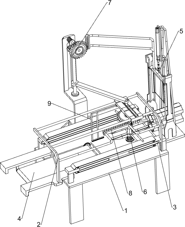
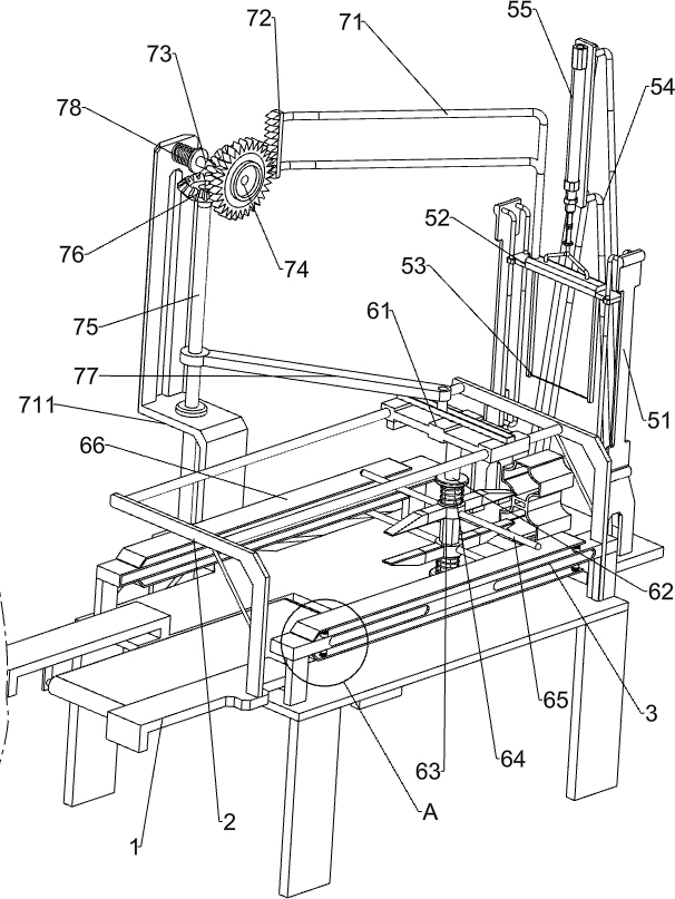
[0025] A blue tile brick carving cutting device for construction engineering, such as Figure 1-3 As shown, it includes a support 1, a first guide rail 2, a fixed plate 3 and a conveyor belt 4. The top of the support 1 is connected with the first guide rail 2, and the front and rear sides of the top of the support 1 are connected with a fixed plate 3. The support 1 The conveyor belt 4 is rotatably connected to the left side, and also includes a cutting assembly 5 and a clamping assembly 6 . The cutting assembly 5 is provided on the support 1 , and the clamping assembly 6 is provided between the first guide rail 2 and the fixing plate 3 .
[0026] The cutting assembly 5 includes a second guide rail 51, a first slide plate 52, a cutting steel wire 53, a fixed frame 54 and an air cylinder 55. The right side of the top of the support 1 is connected with a second guide rail 51, and the second guide rail 51 is slidably connected with a second guide rail 51. A slide plate 52, the bot...
Embodiment 2
[0030] On the basis of Example 1, such as figure 2 As shown, a swing assembly 7 is also included, and the swing assembly 7 includes a mounting frame 711, a first extension frame 71, a driving rack 72, a first rotating shaft 73, a torsion spring 78, a first one-way gear 74, and a second rotating shaft 75 , a bevel gear 76 and a connecting rod 77, the rear side of the top of the support 1 is connected with a mounting frame 711, the top of the first slide plate 52 is connected with a first extension frame 71, and the first extension frame 71 is connected with a driving rack 72, and the mounting frame 711 The upper part is rotatably connected with the first rotating shaft 73, and the first rotating shaft 73 is connected with the first one-way gear 74, the first one-way gear 74 will mesh with the driving rack 72, and the lower part of the mounting frame 711 is rotatably connected with the second rotating shaft 75 , the top of the second rotating shaft 75 and the first rotating sha...
Embodiment 3
[0033] On the basis of Example 2, such as Figure 4 As shown, a rotating assembly 8 is also included. The rotating assembly 8 includes a connecting frame 81, a transmission rack 82 and a second one-way gear 83. The first guide rail 2 is connected with a connecting frame 81, and the connecting frame 81 is connected with a transmission gear. A second one-way gear 83 is connected to the bar 82 and the diamond-shaped rod 62 , and the second one-way gear 83 will mesh with the transmission rack 82 .
[0034] When the rhombic rod 62 reciprocates left and right, it drives the second one-way gear 83 to reciprocate left and right. When the second one-way gear 83 moves to the left to mesh with the transmission rack 82, the second one-way gear 83 continues to move through the transmission rack. 82 rotates, and the transmission rack 82 rotates to drive the diamond bar 62 to rotate. When the second one-way gear 83 moves to disengage with the drive rack 82, the diamond bar 62 just rotates on...
PUM
 Abstract
Description
Claims
Application Information
 - R&D
- Intellectual Property
- Life Sciences
- Materials
- Tech Scout
- Unparalleled Data Quality
- Higher Quality Content
- 60% Fewer Hallucinations
Browse by: Latest US Patents, China's latest patents, Technical Efficacy Thesaurus, Application Domain, Technology Topic, Popular Technical Reports.
© 2025 PatSnap. All rights reserved.Legal|Privacy policy|Modern Slavery Act Transparency Statement|Sitemap|About US| Contact US: help@patsnap.com


