
Cement grinding system and method

A technology of cement powder and dust collection system, which is applied in chemical instruments and methods, solid separation, filter and sieve, etc. It can solve the problems of low grinding efficiency, high operating cost, and large installed power, so as to prevent over-grinding and improve energy utilization. The effect of high efficiency and low installed power

Pending Publication Date: 2020-11-13
CHENGDU LEEJUN IND
View PDF0 Cites 1 Cited by
  • Summary
  • Abstract
  • Description
  • Claims
  • Application Information

AI Technical Summary

Problems solved by technology

However, this system will allow some materials that do not need to be pre-grinded to enter the roller press, resulting in a reduction in the effective volume of the roller press and affecting the extrusion efficiency of the roller press.
The ball mill used in this system adopts an asynchronous motor drive system, which has disadvantages such as high power consumption, large floor area, high operating cost, low energy utilization rate, and large installed power.
The powder separator used in this system is usually a two-separation powder separator. The unqualified materials must be returned to the ball mill to continue grinding, so that the production capacity of the ball mill cannot be fully released, and the grinding efficiency is low.

Method used


Image

  • Cement grinding system and method

Examples


Embodiment 1

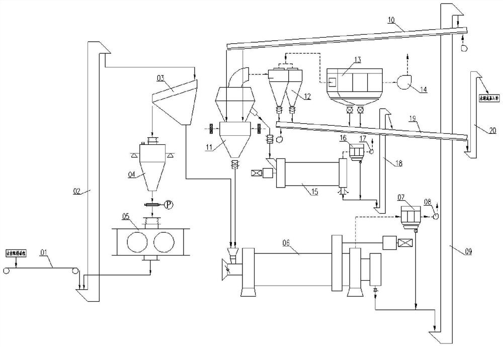
[0040] A cement grinding system such as figure 1 As shown, it includes a vibrating screen 03, a steady flow and constant weight bin 04, a roller press 05, a ball mill 06, a double-rotor powder separator 11, a stirring mill 15 and a dust collection system. The vibrating screen 03 includes an outlet on the sieve and a screen The lower outlet, wherein the outlet under the sieve is connected to the feed inlet of the ball mill 06, the outlet on the sieve is connected to the feed inlet of the steady flow constant weight bin 04, and the outlet of the steady flow constant weight bin 04 is connected to the feed of the roller press 05 The discharge port of the roller press 05 is connected through the hoist 02 and returns to the vibrating screen 03; the double-rotor powder separator 11 includes a bottom discharge port, a waist discharge port and a top air discharge port, wherein the top discharge port The tuyere is connected to the finished product collection system, the waist discharge ...


PUM


Abstract

The invention discloses a cement grinding system and method, and relates to the technical field of cement production. The cement grinding system comprises a vibrating screen, a steady flow constant weight bin, a roller press, a ball mill, a double-rotor powder concentrator, a stirring mill and a dust collecting system, wherein a screen lower outlet of the vibrating screen is connected with a feeding port of the ball mill; a screen upper outlet of the vibrating screen is connected with a feeding port of the steady flow constant weight bin; a discharging port of the steady flow constant weight bin is connected with a feeding port of the roller press; a discharging port of the roller press is connected with and returns to the vibrating screen; a top air outlet of the double-rotor powder concentrator is connected with a finished product collecting system; a waist discharging port of the double-rotor powder concentrator is connected with a feeding port of the stirring mill; a bottom discharging port of the double-rotor powder concentrator is connected with a feeding port of the ball mill; and a discharging port of the ball mill is connected with and returns to the feeding port of the double-rotor powder concentrator. According to the cement grinding system and method, materials which do not need to be extruded by the roller press or ground by the ball mill can be separated out according to different material particle sizes; the electric energy loss of the ball mill is reduced; and the electric energy loss of the cement grinding system is greatly reduced.

Description

technical field [0001] The invention relates to the technical field of cement production, in particular to a cement grinding system and method. Background technique [0002] Cement grinding is the final process of cement manufacturing and also the process that consumes the most electricity. Its main function is to grind the cement clinker to a suitable particle size, form a certain particle gradation, increase its hydration area, accelerate the hydration rate, and meet the requirements of cement paste coagulation and hardening. Reducing the comprehensive power consumption of cement production has become the focus of cement enterprises. [0003] The existing cement grinding technology usually adopts a combined grinding system, and its technological process is as follows: after the material is pre-grinded by a roller press, the fine material is screened out and enters a ball mill for final powder, and then passes through a powder classifier and a dust collector. The system s...

Claims


Application Information

Patent Timeline
IPC IPC(8): B02C21/00B02C23/16B02C23/08B07B1/28C04B7/52
CPCB02C21/00B02C23/16B02C23/08B07B1/28C04B7/52B02C2023/165
Inventor 何亚民丁亚卓徐智平
Owner CHENGDU LEEJUN IND
Learn More