Efficient cement ball mill internal structure

A cement mill and internal structure technology, applied in the field of mill equipment, can solve problems such as not much improvement in grinding effect, increase in mill load, and insufficient lifting height, so as to avoid over-grinding, increase throwing height, good grinding effect

Inactive Publication Date: 2018-08-17
达州市唐氏铸钢有限公司
View PDF9 Cites 5 Cited by
  • Summary
  • Abstract
  • Description
  • Claims
  • Application Information

AI Technical Summary

Problems solved by technology

However, in the actual production process, the stepped liner or corrugated liner commonly used in existing cement mills has insufficient lifting height and small impact, resulting in poor abrasiveness of the mill, low output, and high power consumption.
At the same time, in order to improve the grinding effect of existing cement mills, a certain number of activation liners are usually installed in the mill. However, the activation liners are installed in the mill in the direction of the clockwise rotation of the mill, and the activation effect is not good. The weight increases the load on the mill, and the grinding effect has not been improved much

Method used


Image

  • Efficient cement ball mill internal structure
  • Efficient cement ball mill internal structure
  • Efficient cement ball mill internal structure

Examples


Embodiment Construction

[0032] In order to enable those skilled in the art to better understand the technical solution of the present invention, the present invention will be further described in detail below in conjunction with the accompanying drawings.

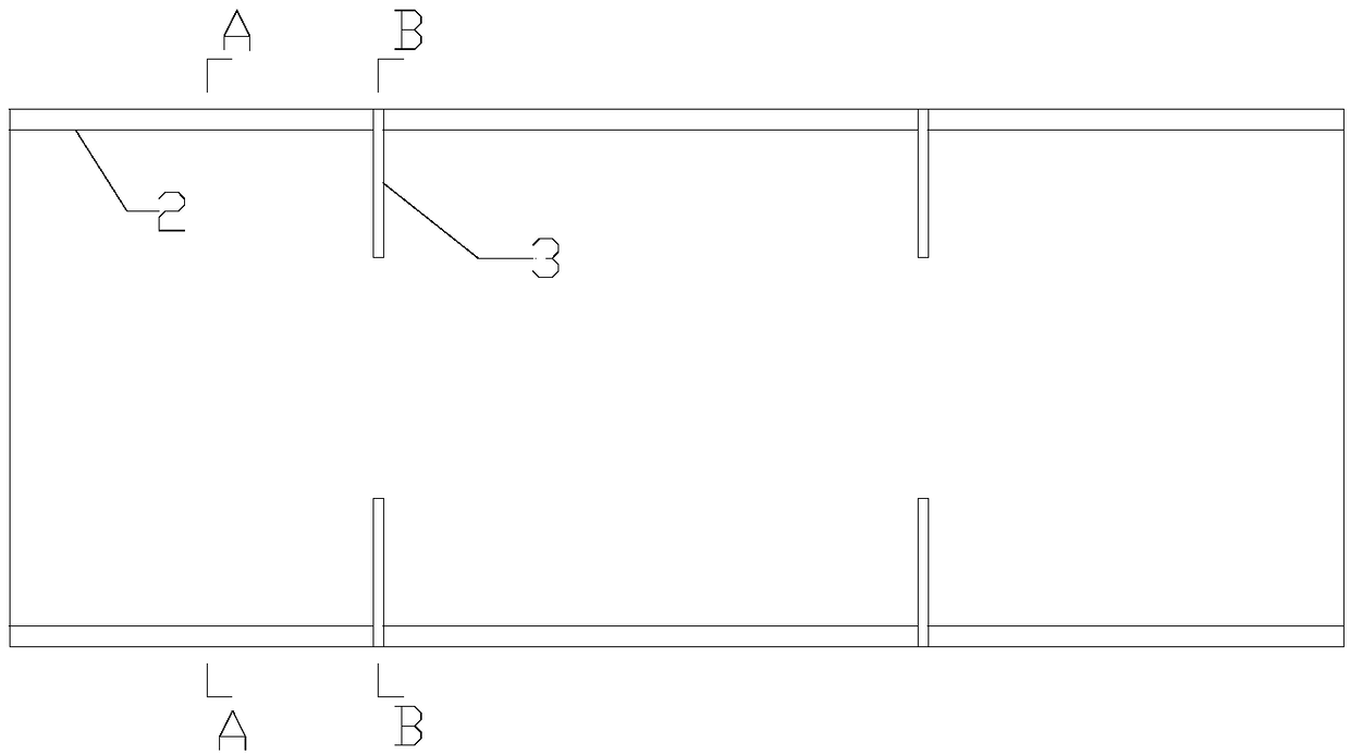
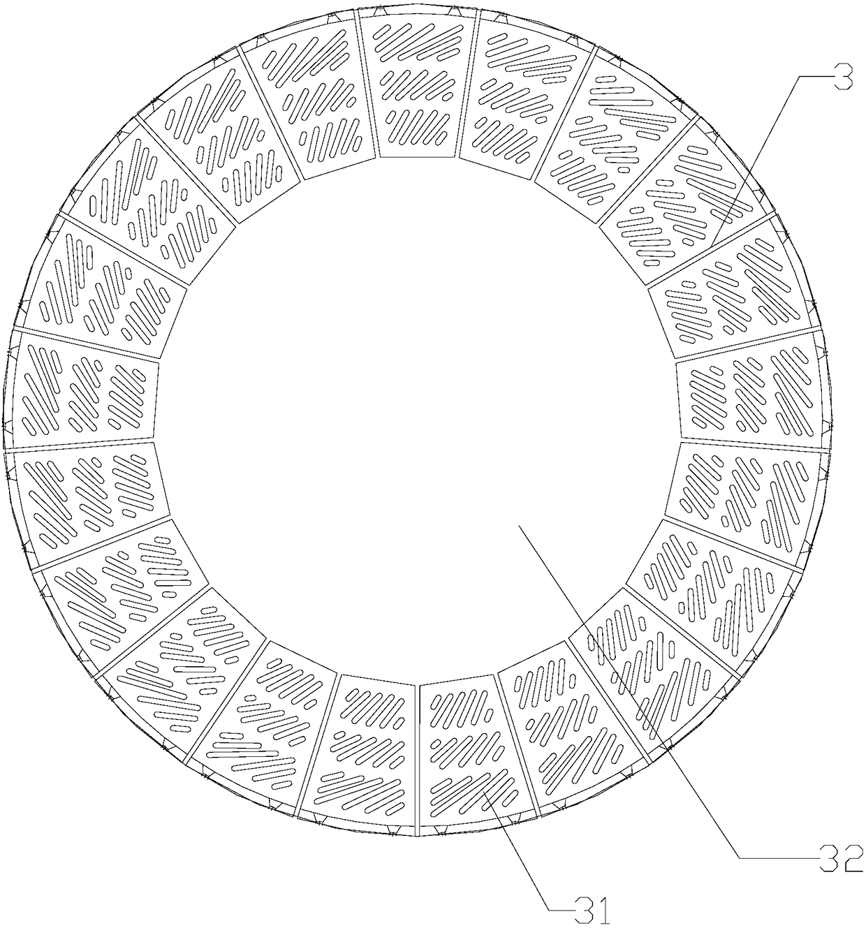
[0033] see Figure 1 to Figure 3 , the present invention provides a cement mill liner structure, which includes a lifting liner 1 installed on the inner wall of the cement mill cylinder, a lifting force distance changing device 2 and a compartment material control plate 3; the lifting liner 1 Install longitudinally along the axial direction of the cement mill cylinder, and transversely install sequentially along the circumferential direction of the cement mill cylinder. Between the adjacent lifting liners in the circumferential direction, the parabolic lug end of one lifting liner is connected to the non-parabolic end of the other lifting liner. The bump end is in contact; the lifting distance variable device 2 is installed longitudinally along th...


PUM


Abstract

The invention discloses an efficient cement ball mill internal structure which comprises lifting lining plates, lifting force variable-distance devices and partition material control plates. The lifting lining plates are mounted on the inner wall of a cement ball mill barrel, the lifting force variable-distance devices are arranged at six equal division points in the circumferential direction of the inner wall of the cement ball mill barrel, the partition material control plates are arranged along the length direction of the cement ball mill barrel at intervals of certain distances, and the lifting lining plates are arranged on the remaining portions of the cement ball mill barrel. The efficient cement ball mill internal structure has the advantages that the lifting lining plates and the lifting force variable-distance devices are used with one another, novel 'L'-shaped structures are adopted, thrust can be generated for grinding media and materials when a mill rotates, and accordinglygrinding effects can be improved; the partition material control plates are arranged at intervals of the certain distances, and accordingly material running due to increase of tossing heights can becontrolled; grate gaps are spirally reserved in a distributed manner, and accordingly the problem that existing grinding media are clamped and embedded in existing grate gaps and block the existing grate gaps can be solved; the efficient cement ball mill internal structure has a good material self-sieving function and is high in discharge speed, excessive grinding phenomena can be prevented, and good ventilation and cooling effects can be realized.

Description

technical field [0001] The invention relates to a high-efficiency cement grinding internal structure, which belongs to the technical field of grinding equipment. Background technique [0002] Cement mill, also known as cement ball mill, is the main equipment for grinding cement clinker in the cement production process. The working principle of the cement mill is that the material enters the mill from the feeding device. The inner wall of the mill is equipped with a stepped liner or a corrugated liner. The mill is equipped with grinding bodies of different specifications, such as steel balls. After the ball is brought to a certain height, it falls down, causing heavy impact and grinding on the material. However, in the actual production process, the stepped liner or corrugated liner commonly used in existing cement mills has insufficient lifting height and small impact, resulting in poor abrasiveness of the mill, low output, and high power consumption. At the same time, in ...

Claims


Application Information

Patent Timeline
Patent Type & Authority Applications(China)
IPC IPC(8): B02C17/22B02C17/10B02C17/18B02C23/10
CPCB02C17/10B02C17/18B02C17/22B02C23/10
Inventor 唐建成
Owner 达州市唐氏铸钢有限公司
Why Eureka
Try Eureka