Image change detection method and device integrating residual network and U-Net network, storage medium and equipment

An image change detection and storage medium technology, which is applied in image enhancement, image analysis, image data processing, etc., can solve problems such as being susceptible to light and shadow, image resolution reduction, and low detection accuracy, so that it is not easy to overfit, Improved resolution and intuitive network architecture

Pending Publication Date: 2020-11-10
云南电网有限责任公司输电分公司
View PDF0 Cites 3 Cited by
  • Summary
  • Abstract
  • Description
  • Claims
  • Application Information

AI Technical Summary

Problems solved by technology

At present, changes in image data captured by remote sensing, drones, and close-ups at different times will have problems with low detection accuracy. The main reasons are: (1) Traditional change detection methods generally use threshold methods or simple feature extraction, and the accuracy is not high. And it is easily affected by the factors of light and shadow; (2) using the recognized convolutional neural network framework for change detection will lead to a decrease in the resolution of the image; (3) the use of ordinary convolutional neural networks will cause the problem of gradient disappearance

Method used


Image

  • Image change detection method and device integrating residual network and U-Net network, storage medium and equipment
  • Image change detection method and device integrating residual network and U-Net network, storage medium and equipment
  • Image change detection method and device integrating residual network and U-Net network, storage medium and equipment

Examples


Embodiment Embodiment 1

[0039] see figure 1 , the present embodiment provides an image change detection method of a fusion residual network and a U-Net network, comprising the following steps:

[0040] Step S1: The encoding part of the U-Net network is transformed into a residual network, and the decoding part remains unchanged.

[0041] In this step, if Figure 4 As shown, the U-net network is named for its structure resembling the letter 'U', which is a deformation of the fully convolutional neural network. Existing samples can be effectively used through data augmentation. The U-net network is mainly composed of two parts: the contraction path and the expansion path. The contraction path is used to capture context information, and feature extraction is performed on sample data through convolution; The extended path combines the underlying feature map with the feature map of the upper layer during the feature upsampling process, retains the feature information extracted in the convolution process...

Embodiment 2

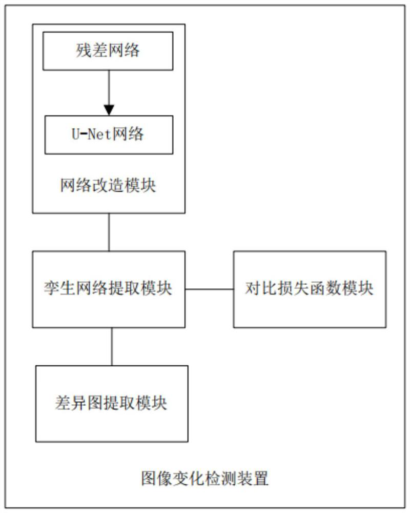
[0053] see figure 2 , the present embodiment provides an image change detection device, including:

[0054] A network transformation module, used to transform the encoding part of the U-Net network into a residual network;

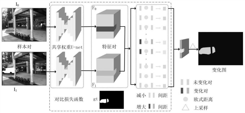
[0055] The twin network extraction module is used to generate the twin network from the transformed U-Net network and extract the abstract features of images in different periods;

[0056] Contrastive loss function module for training the U-Net twin network;

[0057] The difference map extraction module is used to extract the changing regions of images in different periods using the U-Net Siamese network.

Embodiment 3

[0059] This embodiment provides an image change detection storage medium, on which a computer program is stored, and when the computer program is executed by a processor, the above image change detection method can be realized.


PUM


Abstract

The invention relates to the field of change detection of computer vision, in particular to an image change detection method integrating a residual error network and a UNet network, which comprises the following steps of: transforming a coding part of the UNet network into the residual error network, and keeping a decoding part unchanged; generating a twin network from the transformed UNet network, and respectively extracting abstract features of the images in different periods; calculating the difference between the network output and the reference image by using a comparison loss function, and training the modified UNet network; using the trained network to calculate difference graphs of images in different periods, and using an image segmentation technology to search an optimal segmentation threshold to extract a change area; according to the method, the residual network is introduced, so that the problem of gradient disappearance in the layer-by-layer mapping process is avoided; and the UNet twin network is adopted, so that fewer parameters and less data are required during training, and over-fitting is not easy to occur.

Description

technical field [0001] The invention relates to the field of change detection of computer vision, in particular to an image change detection method, device, storage medium and equipment. Background technique [0002] Scene change detection is a fundamental task in the field of computer vision. Its core idea is to detect changes between multiple images of the same scene taken at different time points. From different perspectives of change, it includes two aspects: semantic changes (changes in regions of interest), noise changes (interference changes), and change detection aims to identify semantic changes in the same scene at different times rather than noise changes. However, in reality, the appearance of noise changes cannot be avoided after all, so the biggest challenge faced by this task is the noise changes caused by various factors (such as: illumination, shadow, viewpoint difference, etc.). Changes are intertwined together, resulting in the phenomenon of "semantic fu...

Claims


Application Information

Patent Timeline
IPC IPC(8): G06T7/00G06T7/11G06T7/136G06N3/04G06N3/08
CPCG06T7/0002G06T7/11G06T7/136G06N3/08G06T2207/10004G06T2207/20081G06T2207/20084G06T2207/20221G06N3/045
Inventor 孙斌蔡澍雨杨亮张雯娟杨凤杨腾
Owner 云南电网有限责任公司输电分公司
Why Eureka
Try Eureka