
A device and method for monitoring the grouting sleeve of an offshore wind turbine and ensuring operation safety

A technology of grouting sleeves and offshore fans, which is applied in complex mathematical operations, instruments, televisions, etc., and can solve the problems of quantitative measurement of the scope and amount of grout leakage, the inability to confirm the integrity of grouting packers, and the inability to ensure the safety of fan sleeves. Monitoring and other issues to achieve the effect of reducing the probability of occurrence

Active Publication Date: 2021-08-31
ZHEJIANG UNIV
View PDF0 Cites 0 Cited by
  • Summary
  • Abstract
  • Description
  • Claims
  • Application Information

AI Technical Summary

Problems solved by technology

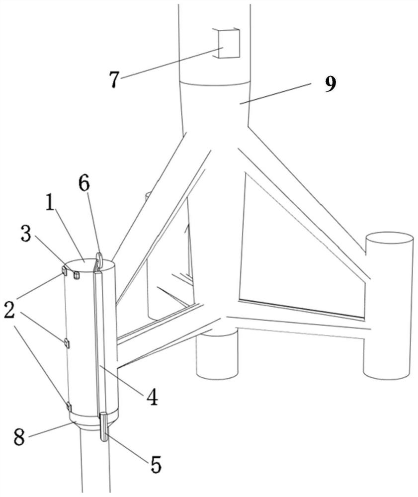
[0004] The purpose of the embodiments of the present invention is to provide a device and method for monitoring the grouting sleeve of an offshore wind turbine and ensuring operation safety, so as to solve the problem in the related art that the integrity of the grouting packer cannot be confirmed during the construction process, and the scope of grout leakage and Quantitative calculation of the amount of slurry leakage, unable to conduct safety monitoring of the long-term operation of the fan sleeve, and unable to guarantee a rapid early warning in case of a situation that endangers the safe operation of the structure

Method used


Image

  • A device and method for monitoring the grouting sleeve of an offshore wind turbine and ensuring operation safety
  • A device and method for monitoring the grouting sleeve of an offshore wind turbine and ensuring operation safety
  • A device and method for monitoring the grouting sleeve of an offshore wind turbine and ensuring operation safety

Examples


Embodiment Construction

[0059] It should be noted that, in the case of no conflict, the embodiments in the present application and the features in the embodiments can be combined with each other. The present invention will be described in detail below with reference to the accompanying drawings and examples.

[0060] It should be noted that the terminology used here is only for describing specific implementations, and is not intended to limit the exemplary implementations according to the present application. As used herein, unless the context clearly dictates otherwise, the singular is intended to include the plural, and it should also be understood that when the terms "comprising" and / or "comprising" are used in this specification, they mean There are features, steps, operations, means, components and / or combinations thereof.

[0061] For the convenience of description, spatially relative terms may be used here, such as "on ...", "over ...", "on the surface of ...", "above", etc., to describe the ...


PUM


Abstract

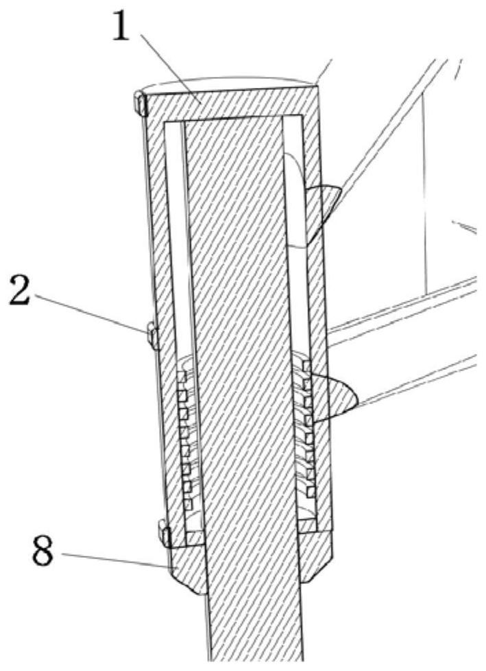
The invention discloses a device and method for monitoring the grouting sleeve of an offshore fan and ensuring operation safety, comprising a grouting sleeve; a slide rail assembly fixed on the grouting sleeve; a binocular camera, a binocular The camera is mounted on the slide rail assembly to check whether the underwater camera grouting sleeve is leaking; the cavity device with through holes is arranged at the lower end of the lower ring plate of the grouting sleeve. The outer diameter of the through hole is larger than the diameter of the pile casing, and its initial state is folded and compressed. After being filled with fillers, the cavity device with the through hole expands inwards and closely fits the outer wall of the pile casing; the terminal is used for When pre-grouting, receive the signal of whether the grouting sleeve is leaking from the binocular camera, and judge whether the grouting packer in the grouting sleeve is damaged. If so, trigger the cavity device with through holes to expand and fit the outer wall of the pile casing ; Receive the position information of the grouting sleeve through the feedback of the binocular camera during the operation period, and obtain the settlement amount of the sleeve through the binocular vision quantitative algorithm.

Description

technical field [0001] The invention belongs to the field of engineering monitoring, and relates to a device and a method for monitoring the grouting sleeve of an offshore fan and ensuring operation safety. Background technique [0002] Offshore wind energy, as a clean and stable renewable energy source, has seen an increase in global wind power generation year by year in the past decade. As the water depth of wind power development increases, more and more wind farms adopt the jacket foundation form. The grouting sleeve is used to connect the jacket and the pile foundation, which is one of the key components to ensure the safety of the support structure of offshore wind turbines. . [0003] At present, because the offshore wind turbine grouting sleeve is constructed underwater, the grouting packer is often damaged or partially detached, and pouring a large amount of grouting materials without knowing the situation at the time of grouting not only wastes a lot of money but ...

Claims


Application Information

Patent Timeline
Patent Type & Authority Patents(China)
IPC IPC(8): E02D27/42E02D27/52E02D15/00H04N7/18G06T7/70G06T7/80G06F17/12
CPCE02D15/00E02D27/425E02D27/52E02D2250/003E02D2250/0061E02D2600/10G06F17/12G06T7/70G06T7/85H04N7/181
Inventor 王振宇李政达
Owner ZHEJIANG UNIV
Learn More