
Rotatable orifice closure

A closed orifice rotary technology, applied in sealing/isolation, wellbore/well parts, earthwork drilling and production, etc., can solve problems such as complicated procedures, affecting grouting effect and quality, and achieve reduced construction costs and convenient construction , Guarantee the effect of grouting quality

Pending Publication Date: 2019-01-18
SINOHYDRO BUREAU 16 CO LTD
View PDF0 Cites 0 Cited by
  • Summary
  • Abstract
  • Description
  • Claims
  • Application Information

AI Technical Summary

Problems solved by technology

When encountering special geological conditions and hole sections, in order to avoid burying the drill, the grouting rod is often moved, but the seal of the above rubber ball limits the degree of freedom of the grouting rod. To move the grouting rod, the grouting pump must be stopped, and the gland on the sealer must be opened. Movable grouting rod, the process is relatively complicated, which greatly affects the grouting effect and quality

Method used


Image

  • Rotatable orifice closure
  • Rotatable orifice closure
  • Rotatable orifice closure

Examples


Embodiment 1

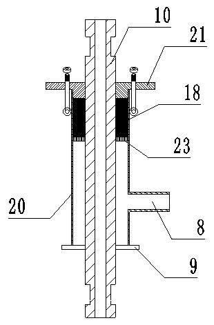
[0022] Example 1, such as image 3 As shown, a rotatable orifice closure is improved on the basis of the existing orifice closure. The skeleton oil seal is used to replace the rubber ball for sealing, and the rolling bearing is used to make the grouting rod rotate while grouting, effectively preventing buried drill. Specific as image 3 As shown, it includes a casing 20, a grouting rod 10, an upper gland 21, a skeleton oil seal 11, a snap ring 12, a rolling bearing 13, a rotating power 30, and a control system. The inner wall of the casing is fixed with a gasket 23, and the skeleton oil is sealed on the top of the gasket. On the surface, the inner wall of the shell above the skeleton oil seal is designed with a snap ring groove that matches the snap ring. The rolling bearing is fixed above the snap ring. The side of the shell is designed with a slurry return port 8 that communicates with the center hole. Below, the slurry return port communicates with the pressure gauge 6, a...

Embodiment 2

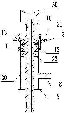
[0023] Example 2, such as Figure 4 As shown, a rotatable orifice closure device includes a casing 20, a grouting rod 10, an upper gland 21, a skeleton oil seal 11, a snap ring 12, a rolling bearing 13, a rotating power 30, and a control system. The casing is divided into an upper casing Two parts 201 and lower shell 202 are connected between the upper shell 201 and the lower shell 202 by the lower cover 7, and the two are closed and connected, and a skeleton oil seal is fixed under the lower cover to effectively prevent the slurry below from entering the upper shell Inside. The lower shell mainly plays the role of slurry return, and the side of the lower shell is designed with a slurry return port 8 communicating with the central hole, and the lowermost end of the lower shell is a flange 9. The upper shell is mainly used to seal the grouting rod and provide the function of rotation. The upper shell is sequentially equipped with a gasket 3, a rolling bearing 13, a snap ring 1...

Embodiment 3

[0024] Example 3, such as Figure 5 As shown, a rotatable orifice closure device includes a casing 20, a grouting rod 10, an upper gland 21, a skeleton oil seal 11, a snap ring 12, a rolling bearing 13, a rotating power 30, and a control system. The casing is divided into an upper casing Two parts 201 and lower shell 202 are connected between the upper shell 201 and the lower shell 202 by the lower cover 7, and the two are closed and connected, and a skeleton oil seal is fixed under the lower cover to effectively prevent the slurry below from entering the upper shell Inside. The lower shell mainly plays the role of slurry return, and the side of the lower shell is designed with a slurry return port 8 communicating with the central hole, and the lowermost end of the lower shell is a flange 9. The upper shell is mainly used to seal the grouting rod and provide the function of rotation. The upper shell is sequentially equipped with gasket 3, rolling bearing, snap ring, bearing b...


PUM


Abstract

The invention discloses a rotatable orifice closure, the rotatable orifice closure is characterized by comprising a shell, a grouting rod, an upper gland, a framework oil seal, a snap ring, a rollingbearing, a rotating power and a control system, wherein the inner wall of the shell is fixed with a gasket; the framework oil seal is encapsulated on the upper surface of the gasket; a snap ring groove matched with the snap ring is designed on the inner wall of the shell above the framework oil seal, the rolling bearing is fixed on the upper part of the snap ring, the side face of the shell is provided with a slurry return opening communicated with the central hole, the slurry return opening is positioned below the gasket, the control system is electrically connected with the pressure gauge, The control system is electrically connected with the rotating power, the grouting rod is connected with the rotating power, the pressure of the pressure gauge reaches a set value, and the control system starts, the rotating power drives the grouting rod to rotate. The rotatable orifice closure of the invention is simple in operation, light in construction and high in efficiency; There is no need to pause the grouting machine during the grouting process, and the drill pipe can be driven without opening the orifice closure to the rotatable orifice closure can be repeatedly recycled and the rotatable orifice closure also can reduce the construction cost, effectively ensure the smooth progress of grouting, and ensure the grouting quality.

Description

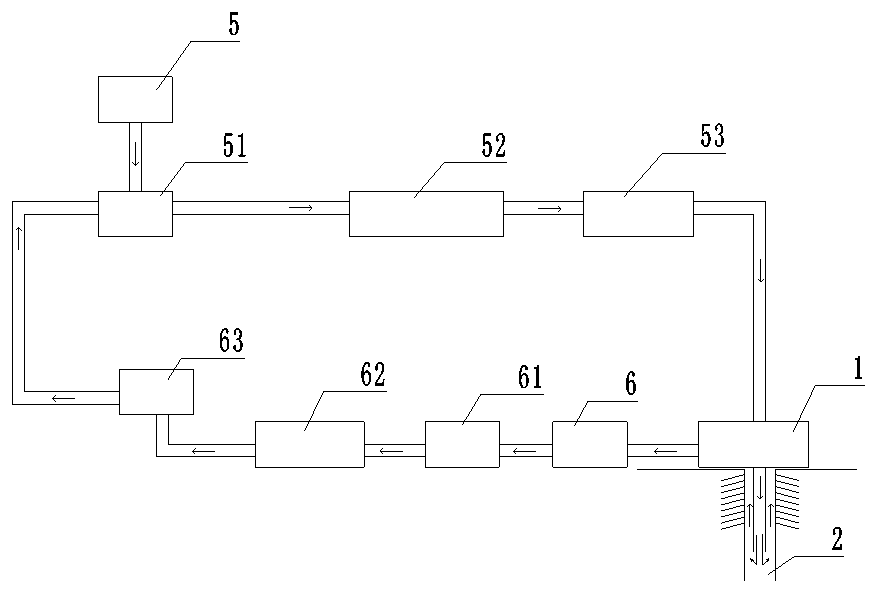
technical field [0001] The invention belongs to the drilling technology, and is especially suitable for an orifice closure for drilling. Background technique [0002] Orifice closed grouting construction process such as figure 1 Shown: According to the design requirements, use a pulping machine to prepare cement slurry, pulping machine 5 → mixing tank 51 (stirring to avoid cement condensation) → grouting pump 52 (pressurizing the slurry, feeding slurry) → slurry inlet flowmeter 53 (for feeding The cement slurry flow in the slurry pipeline is measured) → orifice sealer 1 → grouting hole 2 (slurry circulates in the hole and seals the surrounding cracks) → orifice sealer 1 (returning grout port) → pressure gauge 6 (Measure return slurry pressure) → high pressure valve 61 (adjust pressure) → return slurry flow meter 62 (measure the flow rate of cement slurry in the return slurry pipeline) → specific gravity meter 63 (measure the density of return slurry slurry) → mixing tank 5...

Claims


Application Information

Patent Timeline
Patent Type & Authority Applications(China)
IPC IPC(8): E21B33/13
CPCE21B33/13
Inventor 叶盛茂徐扬鸿阮跃鸿罗德超曹凯刘征刘培昂
Owner SINOHYDRO BUREAU 16 CO LTD
Learn More