
Display panel and manufacturing method thereof

A technology for a display panel and a manufacturing method, which is used in the manufacture of semiconductor/solid-state devices, electrical components, and electrical solid-state devices, etc., can solve the problems of complex processes and difficult etching of the anode layer, and achieves simplified manufacturing processes, improved luminous efficiency, and improved luminous efficiency. The effect of mass production

Inactive Publication Date: 2020-11-06
SHENZHEN CHINA STAR OPTOELECTRONICS SEMICON DISPLAY TECH CO LTD
View PDF5 Cites 7 Cited by
  • Summary
  • Abstract
  • Description
  • Claims
  • Application Information

AI Technical Summary

Problems solved by technology

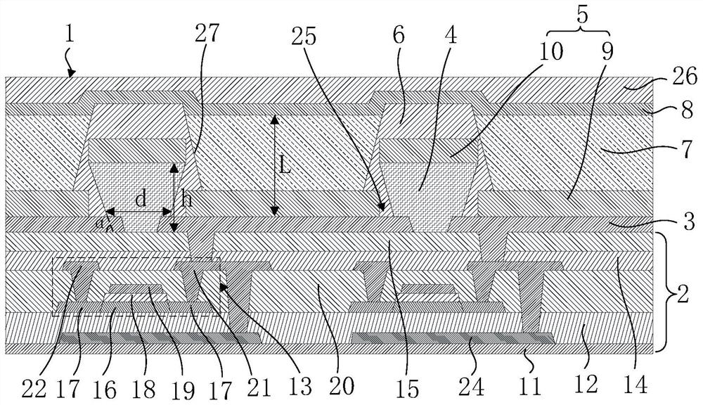
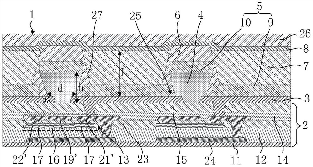
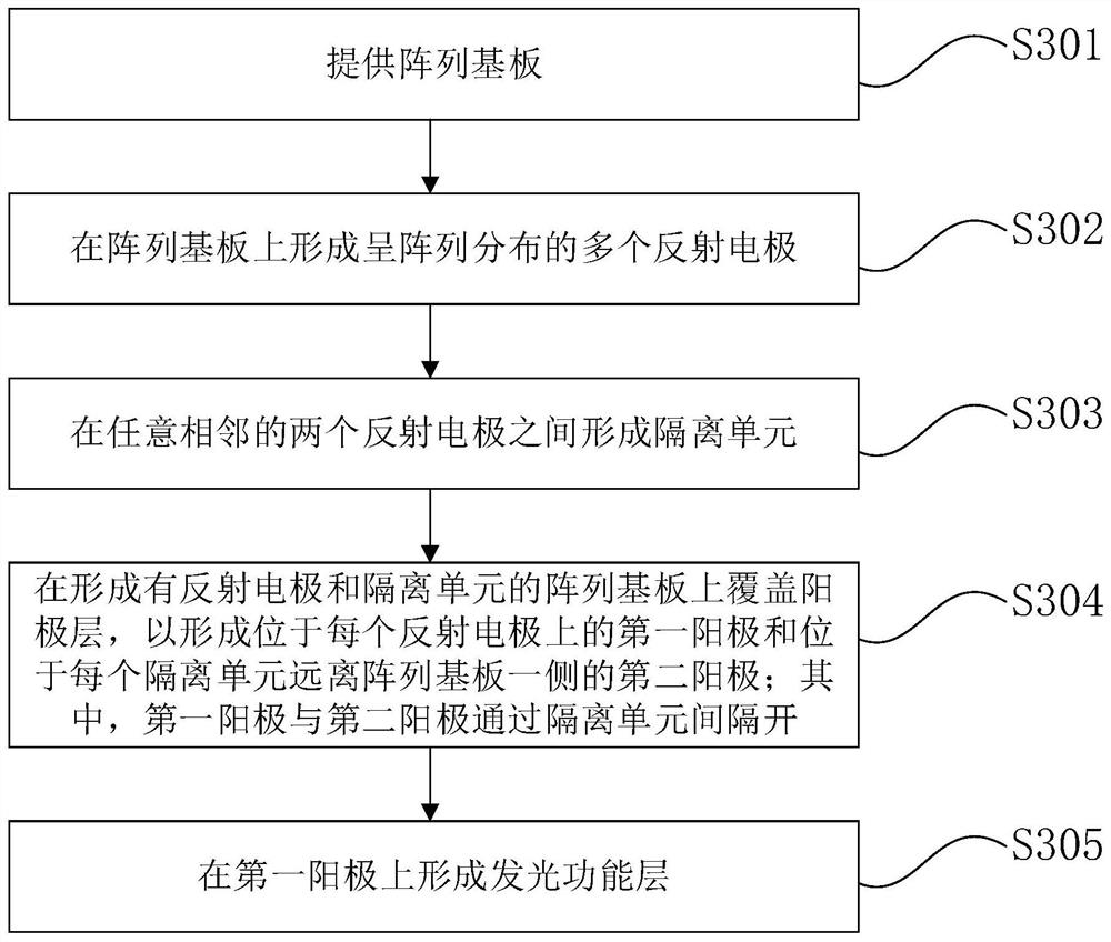
[0005] The present application provides a display panel and a manufacturing method thereof. By disposing an isolation unit between two adjacent reflective electrodes, two adjacent first anodes can be naturally disconnected, and the thickness of the first anode can To adjust the length of the device cavity, it solves the problem that the anode layer with a large thickness is difficult to etch, and at the same time solves the problem of complex process caused by setting a gasket between the anode layer and the reflective electrode to adjust the length of the device cavity

Method used


Image

  • Display panel and manufacturing method thereof
  • Display panel and manufacturing method thereof
  • Display panel and manufacturing method thereof

Examples


Embodiment Construction

[0043] The technical solutions in the embodiments of the present application will be clearly and completely described below in conjunction with the drawings in the embodiments of the present application. Apparently, the described embodiments are only some of the embodiments of this application, not all of them. Based on the embodiments in this application, all other embodiments obtained by those skilled in the art without making creative efforts belong to the scope of protection of this application.

[0044] In the description of the present application, it should be understood that the terms "center", "longitudinal", "transverse", "length", "width", "thickness", "upper", "lower", "front", " Orientation indicated by rear, left, right, vertical, horizontal, top, bottom, inside, outside, clockwise, counterclockwise, etc. The positional relationship is based on the orientation or positional relationship shown in the drawings, which is only for the convenience of describing the a...


PUM


Abstract

The invention discloses a display panel and a manufacturing method thereof. The display panel comprises an array substrate, a plurality of reflecting electrodes, a plurality of isolation units, an anode layer and a light-emitting function layer. The plurality of reflecting electrodes are positioned on the array substrate and are distributed in an array manner; one isolation unit is arranged between any two adjacent reflecting electrodes; the anode layer comprises a first anode located on each reflecting electrode and a second anode located on the side, away from the array substrate, of each isolation unit, and each first anode and the adjacent second anode are spaced through the corresponding isolation unit; and the light-emitting function layer is located on the first anodes. According tothe invention, two adjacent first anodes can be naturally disconnected through the isolation unit, and the cavity length of the device can be adjusted through the thickness of the first anodes.

Description

technical field [0001] The present application relates to the field of display technology, in particular to a display panel and a manufacturing method thereof. Background technique [0002] Top-emitting OLED (Organic Light Emitting Diode, Organic Light Emitting Diode, Organic Light Emitting Diode, Organic Light Emitting Diode) device has always been a difficult problem in the research and development of OLED devices. One of the main factors affecting the luminous efficiency of the OLED device and the accurate control of the luminous wavelength is: the control of the cavity length of the OLED device (the cavity length generally refers to the direct distance from the reflective electrode at the bottom of the anode to the cathode). Due to the influence of the microcavity effect, the luminous efficiency of each sub-pixel (sub-pixel) and the position of the pop-up are not optimized, especially the position accuracy of the light-emitting pop-up is greatly affected, resulting in a ...

Claims


Application Information

Patent Timeline
Patent Type & Authority Applications(China)
IPC IPC(8): H01L27/32H01L51/52H01L51/56
CPCH10K59/12H10K50/818H10K50/852H10K59/1201H10K71/00
Inventor 唐甲
Owner SHENZHEN CHINA STAR OPTOELECTRONICS SEMICON DISPLAY TECH CO LTD
Learn More