Eureka AIR delivers breakthrough ideas for toughest innovation challenges, trusted by R&D personnel around the world.

Fiber-wound reinforced graphite heating tube structure and preparation method thereof

A heating tube and graphite technology, which is applied in the direction of electric heating devices, heating element materials, ohmic resistance heating, etc., can solve the problems of long densification process, prolong service life, poor oxidation resistance, etc., and achieve excellent flexural strength and tensile strength performance, good thermal shock resistance, and good flexural strength

Active Publication Date: 2020-11-03
XIAN CHAOMA SCI TECH
View PDF13 Cites 1 Cited by
  • Summary
  • Abstract
  • Description
  • Claims
  • Application Information

AI Technical Summary

Problems solved by technology

The above method uses the carbon cloth winding forming technology combined with the densification technology to obtain the enhanced graphite heating element structure, but the following problems have not been solved: (1) For the graphite heating tube, because it is generally a slender hollow structure, during the winding process (2) The winding layer has the same structure from the inside to the outside, and it is difficult to meet the different requirements of different application environments for flexural strength, tensile resistance, air erosion resistance, and thermal shock resistance; (3) The densification process is long, which is not conducive to the shortening of the production cycle and the reduction of production costs; (4) The surface is not coated, and the oxidation resistance is poor, which is not conducive to further prolonging the service life

Method used

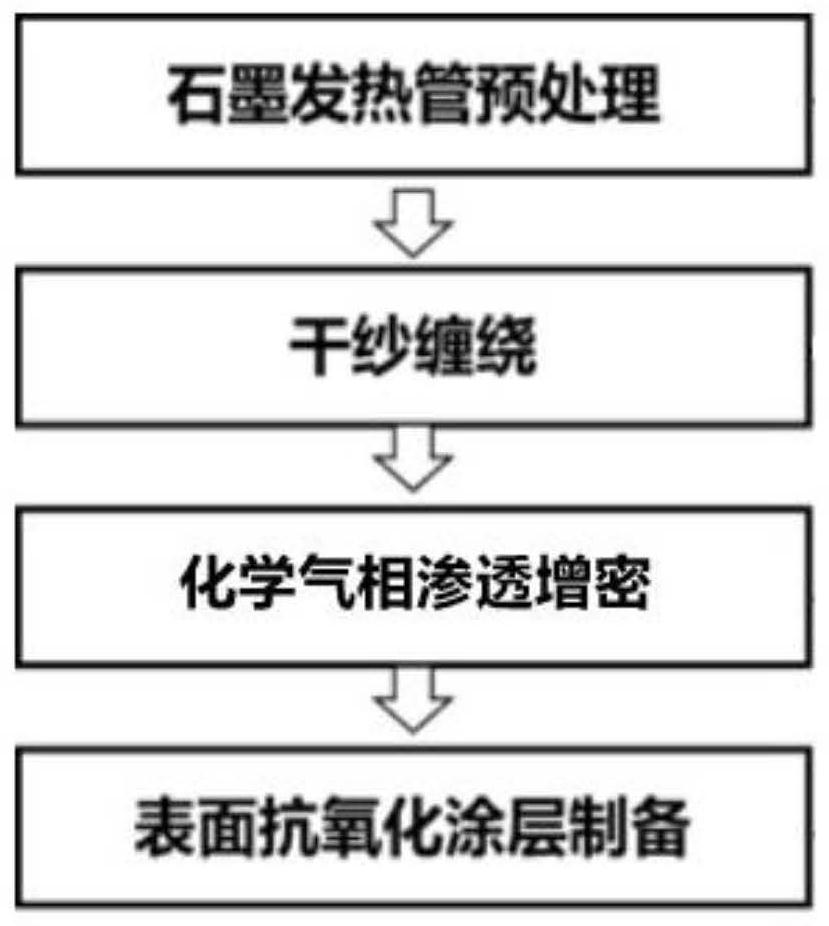

Image

  • Fiber-wound reinforced graphite heating tube structure and preparation method thereof
  • Fiber-wound reinforced graphite heating tube structure and preparation method thereof
  • Fiber-wound reinforced graphite heating tube structure and preparation method thereof

Examples


Embodiment 1

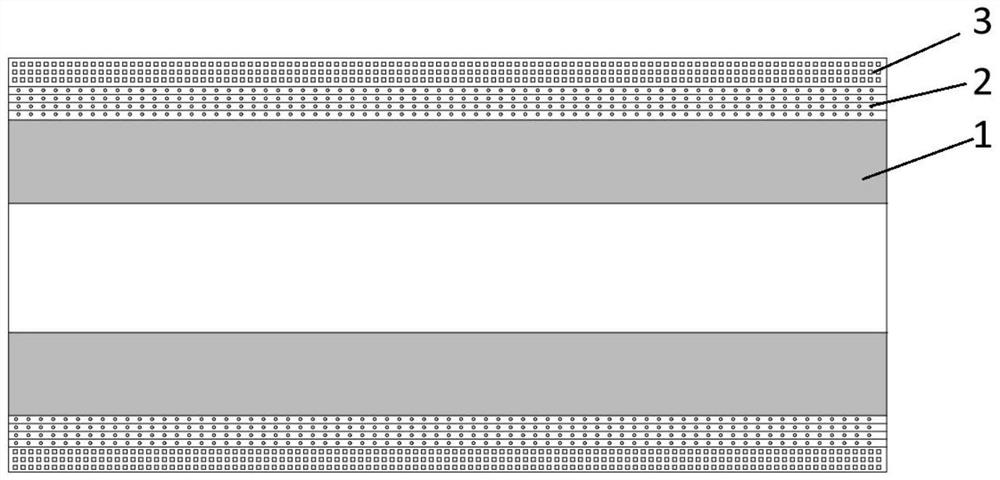
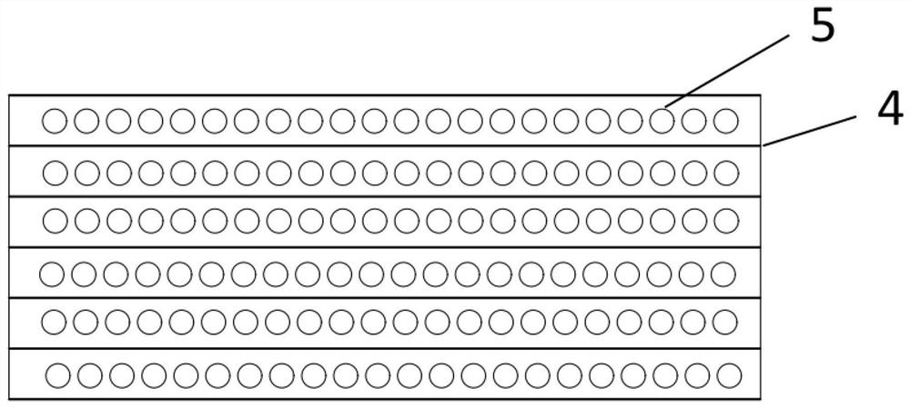
[0040] The fiber-wound reinforced graphite heating tube structure of this embodiment includes a graphite heating tube, a dry yarn winding reinforcement layer coated on the outer surface of the graphite heating tube, and a silicon carbide anti-oxidation coating coated on the surface of the dry yarn winding reinforcement layer, such as figure 2 As shown, the dry yarn winding reinforcement layer is composed of carbon fiber and pyrolytic carbon, and the pyrolytic carbon is evenly distributed in the carbon fiber, as shown in image 3 shown.

[0041] The preparation method of the fiber winding reinforced graphite heating tube structure of this embodiment comprises the following steps:

[0042] Step 1. Pretreatment of graphite heating tube: place the graphite heating tube in a vacuum impregnation furnace and fill it with epoxy resin solution, vacuum impregnate the graphite heating tube at a temperature of 60°C and a pressure of 800Pa, and then use nitrogen gas in the Pressurize and...

Embodiment 2

[0048] The fiber-wound reinforced graphite heating tube structure of this embodiment includes a graphite heating tube, a dry yarn winding reinforcement layer coated on the outer surface of the graphite heating tube, and a silicon carbide anti-oxidation coating coated on the surface of the dry yarn winding reinforcement layer, such as figure 2 As shown, the dry yarn winding reinforcement layer is composed of carbon fiber and pyrolytic carbon, and the pyrolytic carbon is distributed in the carbon fiber along the direction from the inner surface to the outer surface according to the volume content gradient, as shown in Figure 4 As shown, the incremental range of the volume content is 9% / mm.

[0049] The preparation method of the fiber winding reinforced graphite heating tube structure of this embodiment comprises the following steps:

[0050] Step 1. Pretreatment of the graphite heating tube: place the graphite heating tube in a vacuum impregnation furnace and fill it with epox...

Embodiment 3

[0056] The fiber-wound reinforced graphite heating tube structure of this embodiment includes a graphite heating tube, a dry yarn winding reinforcement layer coated on the outer surface of the graphite heating tube, and a silicon carbide anti-oxidation coating coated on the surface of the dry yarn winding reinforcement layer, such as figure 2 As shown, the dry yarn winding reinforcement layer is composed of carbon fiber and pyrolytic carbon, and the pyrolytic carbon is distributed in the carbon fiber along the direction from the inner surface to the outer surface according to the volume content gradient, as shown in Figure 4 As shown, the incremental range of the volume content is 3% / mm.

[0057] The preparation method of the fiber winding reinforced graphite heating tube structure of this embodiment comprises the following steps:

[0058] Step 1. Pretreatment of graphite heating tube: place the graphite heating tube in a vacuum impregnation furnace and fill it with epoxy re...


PUM

PropertyMeasurementUnit
Densityaaaaaaaaaa
Hoop tensile strengthaaaaaaaaaa
Densityaaaaaaaaaa

Abstract

The invention discloses a preparation method of a fiber-wound reinforced graphite heating tube structure. The method comprises the following steps: 1, pretreating a graphite heating tube; 2, winding continuous carbon fiber dry yarn onto the pretreated graphite heating tube; 3, forming a dry yarn winding reinforcing layer; 4, preparing an antioxidant coating to obtain a fiber-wound reinforced graphite heating tube structure. The invention also discloses a fiber-wound reinforced graphite heating tube structure prepared by the method. According to the invention, the pretreated graphite heating tube is subjected to dry yarn belt tension winding, and then densification and surface coating treatment are respectively carried out by sequentially combining CVI and CVD processes, so that the fiber winding reinforced graphite heating tube has better breaking strength, tensile strength, thermal shock resistance and oxidation resistance, the service life is obviously prolonged, and the preparationperiod is shortened; in addition, the fiber winding reinforced graphite heating tube is simple and reliable in structure, and meets the application requirements of various types of graphite heating tubes.

Description

technical field [0001] The invention belongs to the technical field of graphite heating elements, and in particular relates to a fiber winding reinforced graphite heating pipe structure and a preparation method thereof. Background technique [0002] At present, graphite heating tubes are prone to damage during use and maintenance due to their inherent characteristics such as brittleness and poor flexural strength. Especially when induction heating is used, the high-pressure gas needs to pass through the high-temperature graphite induction heating tube, and its speed usually reaches 200m / s~300m / s, and the high-pressure gas will be heated and expanded in the graphite tube, and the graphite induction heating tube Withstand high dynamic pressure and gas expansion pressure, so the graphite induction heating tube is easy to burst and cause failure. [0003] Although carbon / carbon composite materials have the advantages of light weight, high strength, and good fracture toughness, ...

Claims


Application Information

Patent Timeline
IPC IPC(8): C04B35/84C04B35/83C04B35/52C04B35/622C04B41/87H05B3/14
CPCC04B35/83C04B35/522C04B35/622C04B41/87C04B41/009C04B41/5001H05B3/145C04B41/4529
Inventor 赵松宁星华程皓张灵玉党瑞萍彭志刚张永辉代丽娜姚成君王旭鹏
Owner XIAN CHAOMA SCI TECH
Why Eureka
Eureka Blog
Learn More