


Quick Research
Generate reliable direction feasibility study reports for your R&D in just a few steps.

Technical Q&A
Discover and master advanced knowledge NOW. Basics, ideas, possibilities, all at once.

Find Solutions
As an expert in R&D theories, this can generate solutions to your technical problems instantly.

Evaluate Feasibility
Analyze your overall solution with one click, know your potential R&D risks in advance.

Monitor Landscape
Get weekly tech updates, stay abreast of the latest tech innovations and key insights.
2.33-micrometer laser light source and all-fiber cascade narrow linewidth 4.66-micrometer fiber gas laser
A technology of gas laser and narrow line width, which is applied to gas laser components, lasers, laser components, etc., and can solve problems such as lack of laser light sources
- Summary
- Abstract
- Description
- Claims
- Application Information
AI Technical Summary
Problems solved by technology
Method used
Image


Examples
Embodiment 1
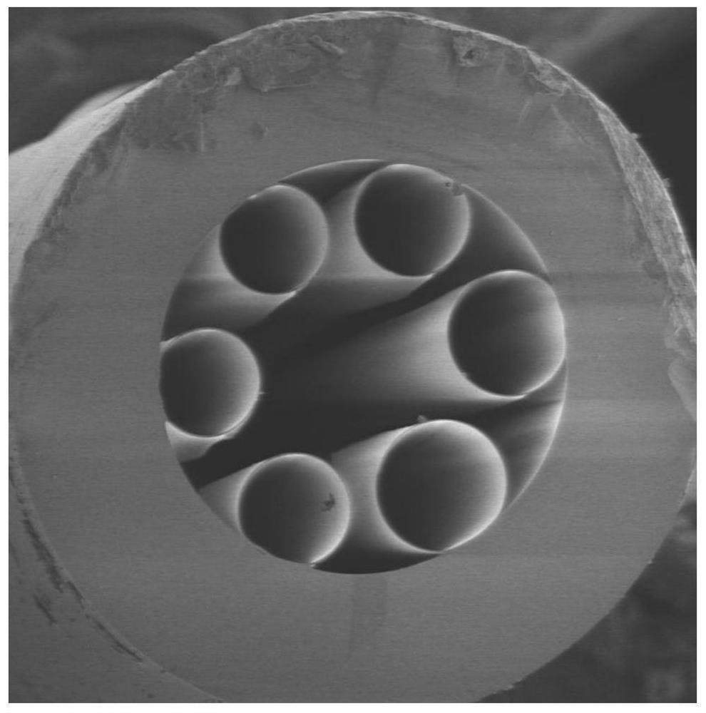
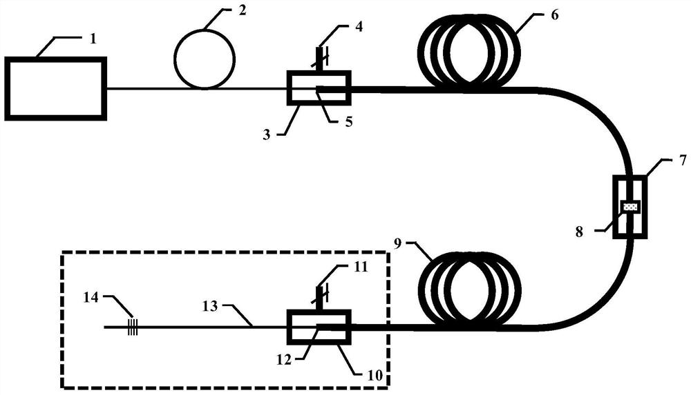
[0042] as attached image 3 As shown, this embodiment provides an all-fiber cascaded narrow-linewidth 4.66 μm fiber gas laser, including a pump source 1, an input solid-core fiber 2, a first-stage anti-resonance hollow-core fiber 6, a second-stage anti-resonance hollow fiber Core fiber 9 and output unit. The first-stage anti-resonance hollow-core fiber 6 and the second-stage anti-resonance hollow-core fiber 9 can be ice cream type anti-resonance hollow-core fibers or nodeless type anti-resonance hollow-core fibers. refer to figure 1 , figure 1 It is an electron micrograph of the cross-section of an ice cream-type anti-resonance hollow-core fiber. refer to figure 2 , 2 is the cross-sectional electron microscope image of the nodeless anti-resonance hollow-core fiber.
[0043] The pumping source 1 is a tunable narrow-linewidth laser light source in the 1.5 μm band, which is used to generate pumping laser light. The output end of the pumping source 1 is connected to an input...
Embodiment 2
[0049] This embodiment 2 provides an all-fiber cascade structure with a narrow linewidth of 4.66 μm fiber gas laser light source, including a pump source 1, an input solid-core fiber 2, a first-stage anti-resonance hollow-core fiber 6, and a second-stage anti-resonance Hollow-core optical fiber 9 and an output unit.
[0050] The difference between Embodiment 2 and Embodiment 1 lies in the implementation of the output unit. refer to Figure 4 , the output unit described in this embodiment is the output window 15 arranged on the third gas cavity 10, the output window 15 has a high transmittance to the 4.66 μm laser, and the output end of the second-stage anti-resonant hollow-core fiber 9 outputs 4.66 μm The μm laser is filtered and output through the output window 15 on the third gas cavity 10 .
Embodiment 3
[0052] Embodiment 3 provides an all-fiber cascaded fiber gas laser light source with a narrow linewidth of 4.66 μm, including a pump source 1, an input solid-core fiber 2, a first-stage anti-resonance hollow-core fiber 6, and a second-stage anti-resonance Hollow-core optical fiber 9 and an output unit.
[0053] The difference between Embodiment 3 and Embodiment 1 and Embodiment 2 lies in the implementation manner of the output unit. refer to Figure 5 In this embodiment, the output unit is a mid-infrared crystal end cap 16 sealed and fixed on the third gas cavity 10 . The mid-infrared crystal end cap 16 is spatially aligned with the output end of the second-stage anti-resonance hollow-core optical fiber 9 and sealed in the third gas chamber 10 . The 4.66 μm laser output from the second-stage anti-resonant hollow-core fiber 9 is coupled into the end cap 16 of the mid-infrared crystal, and finally collimated and output.
[0054] Figure 7 It is a schematic diagram of CO stimul...
PUM
 Abstract
Description
Claims
Application Information
 - R&D Engineer
- R&D Manager
- IP Professional
- Industry Leading Data Capabilities
- Powerful AI technology
- Patent DNA Extraction
Browse by: Latest US Patents, China's latest patents, Technical Efficacy Thesaurus, Application Domain, Technology Topic, Popular Technical Reports.
© 2024 PatSnap. All rights reserved.Legal|Privacy policy|Modern Slavery Act Transparency Statement|Sitemap|About US| Contact US: help@patsnap.com