
Dual-polarized microstrip antenna with guide structure

A microstrip antenna, dual-polarization technology, applied in the direction of radiating element structure, antenna grounding switch structure connection, etc., can solve the problems of not meeting the index, difficult to meet the index requirements, increasing the rejection rate of antenna products, etc., to reduce production costs. , the effect of improving debuggability and improving stability

Active Publication Date: 2020-10-30
SHANGHAI XUANYA TECH CO LTD
View PDF12 Cites 0 Cited by
  • Summary
  • Abstract
  • Description
  • Claims
  • Application Information

AI Technical Summary

Problems solved by technology

A commonly used technical solution for dual-polarized microstrip antennas is to connect the microstrip feeders of two polarized channels to the same square metal patch. Although the structure is simple, the beam of the antenna is wide, resulting in low gain, which is sometimes difficult to meet Index requirements; on the other hand, most microstrip antennas are processed on the PCB board. Once the board is manufactured, the antenna index cannot be adjusted, but processing errors will lead to changes in antenna performance, and even lead to situations that do not meet the index requirements.
In this case, the microstrip antenna does not have any adjustable compensation measures, resulting in an increase in the reject rate of antenna products

Method used


Image

  • Dual-polarized microstrip antenna with guide structure
  • Dual-polarized microstrip antenna with guide structure
  • Dual-polarized microstrip antenna with guide structure

Examples


Embodiment Construction

[0036] The technical solutions in the present invention will be clearly and completely described below in conjunction with the accompanying drawings in the present invention. Obviously, the described inventions are only part of the inventions of the present invention, not all of them. Based on the inventions in the present invention, all other inventions obtained by persons of ordinary skill in the art without making creative efforts belong to the scope of protection of the present invention.

[0037] In describing the present invention, it is to be understood that the terms "middle", "length", "height", "thickness", "upper", "lower", "top", "bottom", "inner", " The orientation or positional relationship indicated by "outside", etc. is based on the orientation or positional relationship shown in the drawings, which is only for the convenience of describing the present invention and simplifying the description, rather than indicating or implying that the referred equipment or el...


PUM


Abstract

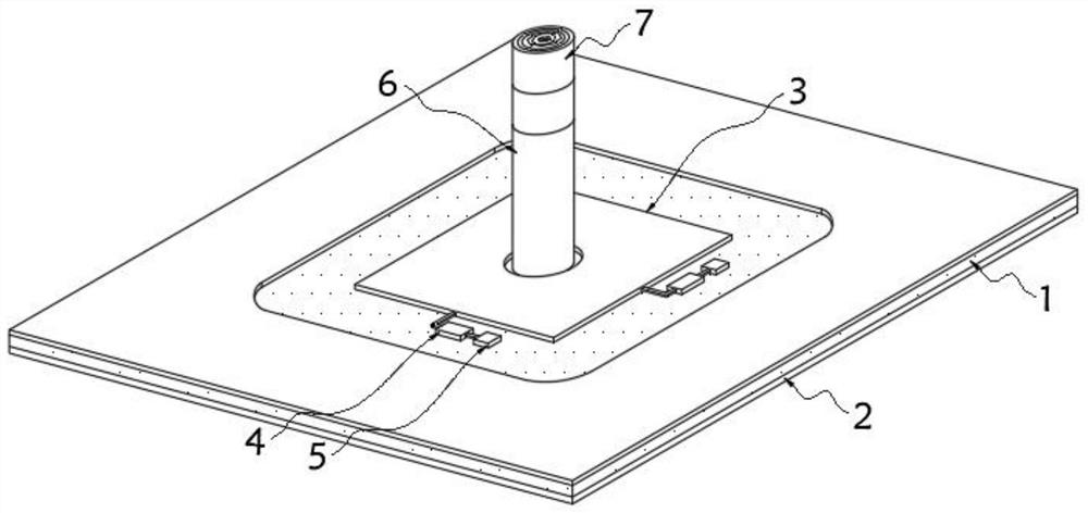
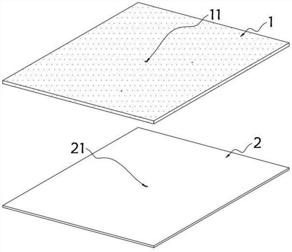
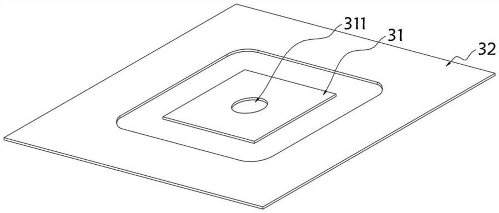
The invention relates to the technical field of microstrip patch antennas. Particularly, the invention relates to a dual-polarized microstrip antenna with a guide structure. The antenna comprises a microwave dielectric substrate, a metal patch assembly is fixed on the top surface of the microwave dielectric substrate; the metal patch assembly comprises a square inner metal patch and a peripheral metal patch, each of two sides of the square inner metal patch is connected with a deploying branch and a feed probe, a metal cylinder is arranged in a through hole in the middle of the square inner metal patch, and the top end of the metal cylinder is connected with a plurality of height adjusting columns. The dual-polarized microstrip antenna with the guiding structure can play a role in guidingan electric wave signal, so that the stability of receiving the electric wave signal by the antenna is improved; meanwhile, the radiation characteristics of the microstrip antenna can be allocated ina small range after a PCB is processed, so that the antenna meets the requirements of specific indexes, and the debugging performance of an antenna product is improved; and in addition, during large-batch production, the rejection rate of products can be reduced through the blending measure, and therefore the production cost is reduced.

Description

technical field [0001] The invention relates to the technical field of microstrip patch antennas, in particular to a dual-polarized microstrip antenna with a guiding structure. Background technique [0002] With the development of mobile communication technology, MIMO multi-antenna technology has become a key technology for Wi-Fi and TD-LTE communication to improve communication quality and efficiency. Using dual-polarized antenna technology to achieve polarization diversity enables polarized multiple access communication to improve channel throughput and utilization. [0003] Among them, the microstrip patch antenna has the advantages of low profile, light weight, small size, low cost, easy integration and array formation, and has been widely studied and applied. A commonly used technical solution for dual-polarized microstrip antennas is to connect the microstrip feeders of two polarized channels to the same square metal patch. Although the structure is simple, the beam o...

Claims


Application Information

Patent Timeline
Patent Type & Authority Applications(China)
IPC IPC(8): H01Q1/38H01Q1/50
CPCH01Q1/38H01Q1/50
Inventor 刘中华
Owner SHANGHAI XUANYA TECH CO LTD
Learn More