
Micro-disturbance cutting-free blasting method

A micro-disturbance, micro-difference initiation technology, used in blasting, earth-moving drilling, surface mining, etc., can solve the problem of inefficient and low-cost solution to weak, broken, narrow ore vein mining, etc., to reduce the amount of construction and explosives. consumption, reduce difficulty and cost, and reduce the amount of drilling construction

Active Publication Date: 2020-10-30
嵩县前河矿业有限责任公司 +1
View PDF7 Cites 1 Cited by
  • Summary
  • Abstract
  • Description
  • Claims
  • Application Information

AI Technical Summary

Problems solved by technology

None of the above methods or methods can efficiently and low-cost solve the approach mining of weak, broken and narrow veins

Method used


Image

  • Micro-disturbance cutting-free blasting method
  • Micro-disturbance cutting-free blasting method
  • Micro-disturbance cutting-free blasting method

Examples


Embodiment 1

[0034] A micro-disturbance non-cutting blasting method, which is used for access mining of weak and broken narrow veins, comprising the following steps:

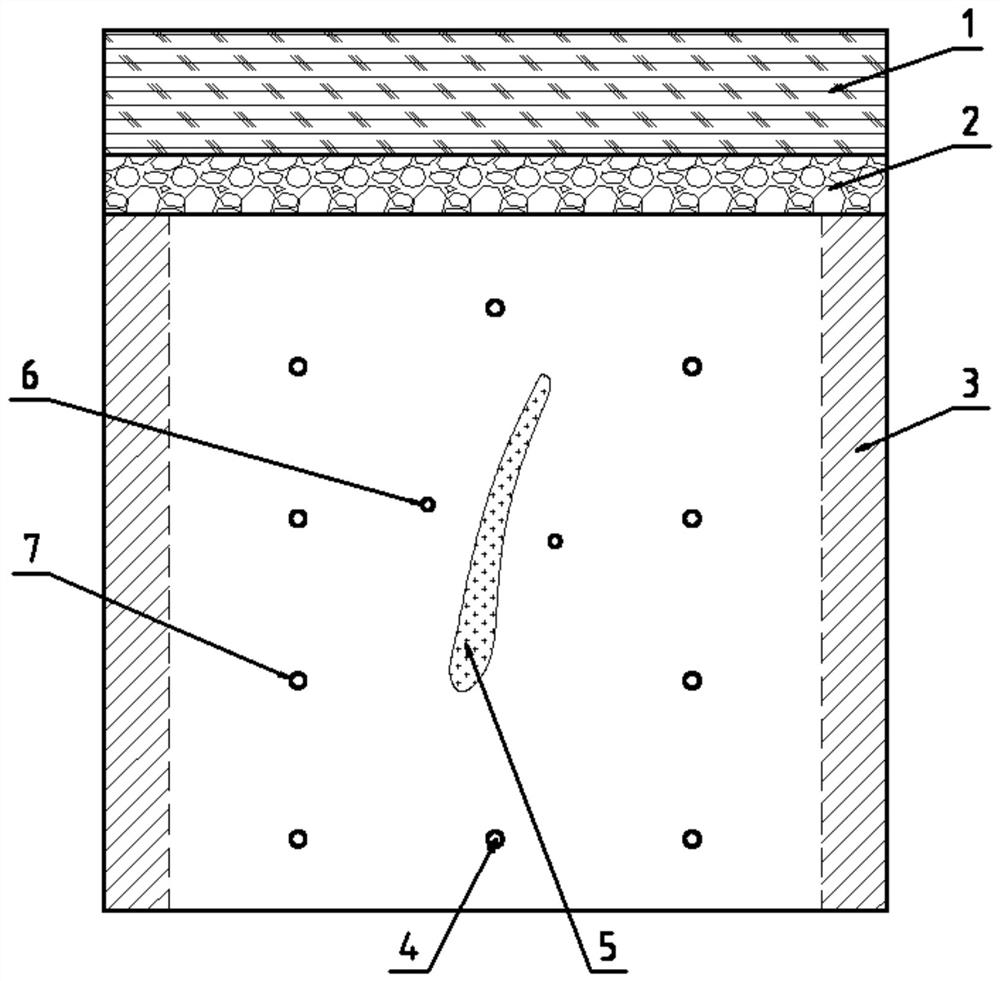
[0035] S1: Determine the position of the main weak structural surface 5 of the face through measurement and data analysis.

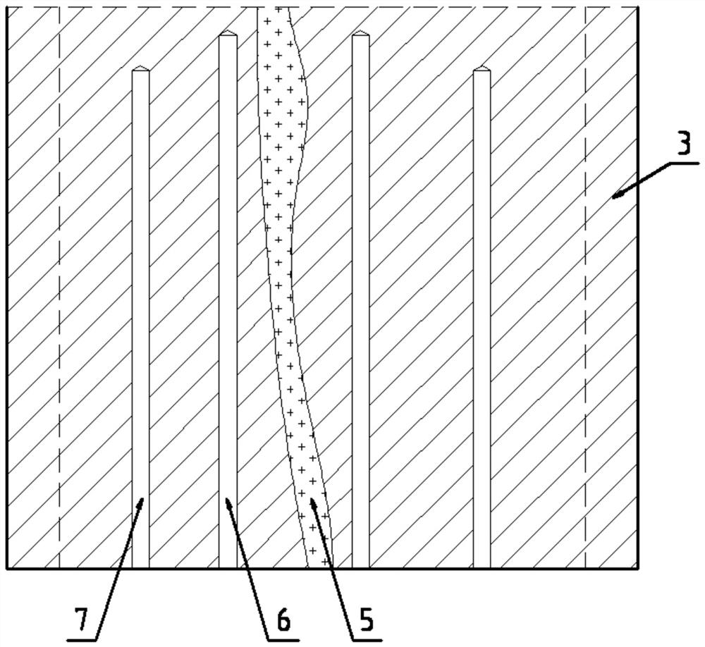
[0036] When drilling rock, according to the development of the face joint fissure surface, look for the main weak structural surface 5. Such as Figure 1-2 As shown, the weak structure surface 5 is an inclined strip-shaped surface located in the middle of the palm surface. Use a compass and tape measure to measure the position of the main weak structural surface 5 of the palm face, and measure the tendency of the weak structural surface 5 through the compass, and obtain the direction of the weak structural surface 5 after adding and subtracting 90°.

[0037] S2: Drill a slotted hole 6 on both sides of the weak structural surface 5, and drill peripheral holes 7 around the face of the tunnel.

[0038]...

Embodiment 2

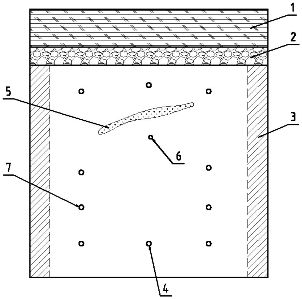
[0048] S1: Determine the position of the main weak structural surface 5 of the face through measurement and data analysis.

[0049] When drilling rock, according to the development of the face joint fissure surface, look for the main weak structural surface 5. Such as image 3As shown, the weak structural surface 5 is a nearly horizontal inclined strip-shaped surface, which is close to the top of the palm face. Use a compass and tape measure to measure the position of the main weak structural surface 5 of the palm face, and measure the tendency of the weak structural surface 5 through the compass, and obtain the direction of the weak structural surface 5 after adding and subtracting 90°.

[0050] S2: Dig a slotted hole 6 at the inner side of the weak structural surface 5 near the center of the palm face, and dig a peripheral hole 7 around the face of the palm.

[0051] In this embodiment, according to the size of the tunnel face and the development of the weak structural sur...


PUM


Abstract

The invention relates to a micro-disturbance cutting-free blasting method which is applied to approach mining of a weak broken narrow lode. The micro-disturbance cutting-free blasting method comprisesthe following steps of (1) through measurement and data analysis, determining a position of a main weak structure face of a tunnel face; (2) digging slotting holes in two sides or one side of the weak structure face, and digging peripheral holes in the periphery of the tunnel face; (3) after carrying out drift stoping on a higher slice, laying a buffer layer with the thickness ranging from 10 to20cm on a bottom plate; (4) reserving wall protection ores with the thickness ranging from 10 to 20cm on two sides of an extracting drift; (5) adopting full-hole charging; and (6) adopting inverse differential initiation. Through the implementation of the steps, the damage degree of blasting vibration to a higher slice cemented filling layer and upper and lower wall rocks is solved fundamentally,and the difficulty and the cost of late supporting are effectively reduced. According to the micro-disturbance cutting-free blasting method provided by the invention, a weak structure of a rock mass body is used as a free face, and the wall protection ores are reserved on two sides of the extraction drift, so that the arrangement number of blast holes is greatly reduced, the construction amount oftrepanning and the consumption of explosives are further greatly reduced, and the comprehensive mining efficiency is improved.

Description

technical field [0001] The invention relates to the field of underground mine blasting, in particular to a micro-disturbance non-cutting blasting method, which is mainly suitable for the approach mining of weak, broken and narrow veins. Background technique [0002] When mining weak and broken narrow veins, the commonly used mining methods include upward approach filling mining method, downward approach filling mining method and upward horizontal layered filling mining method. Among them, the down-fill mining method has the highest proportion of ore. No matter what approach filling method is used for mining, it is necessary to dig holes and cut holes during rock drilling and blasting, and charge the whole hole for blasting. Due to the large vibration of the blasting, the surrounding rock of the weak and broken upper and lower walls will be more broken, and the cost and difficulty of stope support will be further increased, resulting in an increase in the entire mining cost ...

Claims


Application Information

Patent Timeline
Patent Type & Authority Applications(China)
IPC IPC(8): F42D1/00F42D3/04E21C41/22
CPCF42D1/00F42D3/04E21C41/22
Inventor 赵元培黄传宝石建喜刘东锐韩光辉金文辉张森森李日高杨克明李强李士超王玉丁
Owner 嵩县前河矿业有限责任公司
Learn More