
Novel glass fiber reinforced plastic lining concrete combined pipe

A technology that is lined with concrete and glass fiber reinforced plastics, applied in the field of pipelines, can solve problems such as heat dissipation, cracked pipelines, and antifreeze problems

Pending Publication Date: 2020-10-30
德阳市卿发建材物资有限公司
View PDF1 Cites 1 Cited by
  • Summary
  • Abstract
  • Description
  • Claims
  • Application Information

AI Technical Summary

Problems solved by technology

At the same time, the heat dissipation of the existing FRP lined pipe is not good, and a large amount of heat is accumulated inside the pipe, which is not conducive to long-term use
[0004] Chinese patent document 201920848306.7 discloses a glass sand-filled pipeline, in which an electric heating wire is provided on the outer protective wall of the inner pipe to solve the above problems, but it uses electric heating wire to increase electric control, and the cost is high
And electronic products are relatively fragile, therefore, the stability of its antifreeze effect is not good
At the same time, it can only solve the problem of antifreeze, but cannot solve the problem of heat dissipation
[0005] Chinese patent document 201921014189.4 discloses a new type of FRP winding pipe, which dissipates heat through the frame, but it cannot solve the problem of antifreeze
[0006] At the same time, the existing fiberglass-reinforced-concrete composite pipe has a weak radial bonding force between the fiberglass and the concrete layer. Although it can withstand a huge axial jacking force, the tensile force it can withstand is very small. At this time, the FRP layer will produce an outward expansion force, which directly acts on the concrete layer of the outer wall. At this time, the concrete layer will bear a large tensile force, and the concrete layer will swell and shatter, causing the pipeline to rupture.

Method used


Image

  • Novel glass fiber reinforced plastic lining concrete combined pipe

Examples


Embodiment

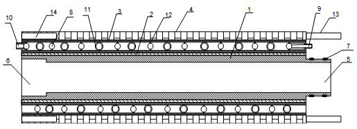
[0021] like figure 1 As shown in the figure, the novel FRP lined concrete composite pipe includes a FRP inner lining layer 1, an elastic interface layer 2, a functional layer 3 and a concrete layer 4 sequentially arranged from the inside to the outside.

[0022] The elastic interface layer 2 is a material with elasticity and a relatively large friction coefficient, such as resin or the like. The frictional force of the elastic interface layer 2 is relatively large, which prevents displacement of the FRP inner lining layer 1 , the functional layer 3 and the concrete layer 4 .

[0023] Further, one end of the FRP lining pipe is provided with a socket 5 , the other end of the FRP lining pipe is provided with a socket 6 , and a groove mounting sealing ring 7 is provided on the socket 5 . The connection of the two combined pipes is realized by a traditional plug-in method. Since it is the prior art, this embodiment will not describe in detail.

[0024] It is worth emphasizing tha...


PUM


Abstract

The invention discloses a novel glass fiber reinforced plastic lining concrete combined pipe. The novel glass fiber reinforced plastic lining concrete combined pipe comprises a glass fiber reinforcedplastic lining layer and a concrete layer, wherein an inserting opening is formed in one end of the glass fiber reinforced plastic lining pipe, a bellmouth is formed in the other end of the glass fiber reinforced plastic lining pipe, a groove is formed in the inserting opening to install a sealing ring, and a functional layer is further arranged between the glass fiber reinforced plastic lining layer and the concrete layer; and the functional layer comprises an annular hollow cylinder made of a steel material. A spiral pipe coaxial with an annular cylinder body is arranged in the annular cylinder body, one end of the spiral pipe is an inserting end extending out of one end of the annular hollow cylinder body, the other end of the spiral pipe is a bearing end extending out of the other endof the annular hollow cylinder body, an annular groove is formed in the outer wall of the bearing end of the spiral pipe and provided with a sealing ring, and when two combined pipes are connected, the spiral pipes of the two combined pipes are connected in an inserting manner; a plurality of second reinforcing ribs are arranged between the spiral pipe and the inner wall of the annular hollow cylinder body to support the spiral pipe; and a first reinforcing rib is arranged between two corresponding inner walls of the annular hollow cylinder.

Description

technical field [0001] The invention relates to the field of pipes, in particular to a novel glass fiber reinforced plastic lined concrete composite pipe. Background technique [0002] The use of glass fiber reinforced plastic as the lining of the concrete pipe is the material with the best corrosion resistance, the best impermeability and the smallest friction system with the fluid in all the concrete pipes at present. The earliest glass fiber reinforced concrete composite pipe includes the inner layer of glass fiber reinforced plastic and the outer layer of concrete. However, with the development of technology and the requirements of application scenarios, a functional layer is further added between the concrete layer and the FRP layer to improve the performance of the composite pipe. For example, in the prior art, there are technical solutions for adding sand interlayers between concrete and FRP, and technical solutions for adding antibacterial layers and anti-permeation...

Claims


Application Information

Patent Timeline
IPC IPC(8): F16L9/14F16L57/02F16L59/02F16L53/70
CPCF16L9/14F16L57/02F16L59/02F16L53/70
Inventor 向继卿
Owner 德阳市卿发建材物资有限公司
Learn More