Gas-liquid mixing and conveying device with three-jaw rotor

一种输送装置、气液混合的技术,应用在用于弹性流体的泵送装置的部件、用于弹性流体旋转活塞式/摆动活塞式的泵组合、旋转活塞式/摆动活塞式的泵部件等方向,能够解决做功性能降低、流量低、发热源本体-工艺气体压缩比、周期气量考虑等问题

Inactive Publication Date: 2020-10-30
YUEQING RUIYI ECONOMIC INFORMATION CONSULTING CO LTD
View PDF0 Cites 0 Cited by
  • Summary
  • Abstract
  • Description
  • Claims
  • Application Information

AI Technical Summary

Problems solved by technology

[0002] In many chemical treatment processes, it is often encountered that the gas-liquid mixture is transported or although the original medium is in the gas phase, the liquid phase is precipitated when the pressure is slightly increased. The gas-liquid two-phase state of most media is related to pressure and temperature, such as water, Water vapor under normal pressure becomes liquid when it cools below 100 degrees, and is separated from the gas. Similarly, isothermally compressing water vapor at 150 degrees can still force it to change into a liquid state. Therefore, if the process medium directly enters the volume Compression is carried out in the pump, and the condensables in it may be precipitated from the gas phase, and the diaphragm type positive displacement pump with low removal efficiency can handle two phases at the same time, such as screw pumps, gear pumps, and claw pumps, which are not convenient to handle liquids with liquid The medium will not only reduce the functional performance, but also damage the machine, while the diaphragm pump is used for gas-liquid transportation, not only has a low flow rate, but also has a large outlet pressure fluctuation
[0003] In the prior art, either the gas is subjected to strong cooling before entering the delivery pump, and the condensate is separated and discharged, or the polymerization inhibitor and coagulation inhibitor are added before the process medium enters the delivery pump. Both methods will Changing the composition of the process medium requires subsequent processing to change back to the original composition in many technological processes: in the first method, when the condensate is directly pressurized and injected into the high pressure test gas in the subsequent step, there is a problem of uneven mixing Problem: The second method not only often cannot find suitable polymerization inhibitors and coagulation inhibitors, but also subsequent re-separation is a troublesome thing
[0004] In addition, when the gas is pressurized and transported, multi-stage compression is often used because the single-stage pressure boost is not enough. The multi-stage gas booster pump in the prior art is compact or other reasons, and the flow channels between the stages are uniform. Located inside the pump, there are only the first-stage air inlet and the last-stage exhaust port to the outside. This design only has the problem of heat dissipation for pure dry gas, because the compression heat of multi-stage compression needs to be dissipated, so the pump body is often installed Some complex internal cooling water channels prevent the machine from overheating and affect some internal fit clearances, which are crucial for pump work; for working conditions containing condensable media, so many stages of gas pressurization The pumps all choose "hard resistance", which is easy to be damaged and requires frequent maintenance
The heat dissipation of the gas delivery pump starts from the external conditions and considers how to enhance the heat dissipation performance, but does not consider the compression ratio and cycle gas volume of the heat source body-process gas

Method used


Image

  • Gas-liquid mixing and conveying device with three-jaw rotor
  • Gas-liquid mixing and conveying device with three-jaw rotor
  • Gas-liquid mixing and conveying device with three-jaw rotor

Examples


Embodiment Construction

[0036] The following will clearly and completely describe the technical solutions in the embodiments of the present invention with reference to the accompanying drawings in the embodiments of the present invention. Obviously, the described embodiments are only some, not all, embodiments of the present invention. Based on the embodiments of the present invention, all other embodiments obtained by persons of ordinary skill in the art without making creative efforts belong to the protection scope of the present invention.

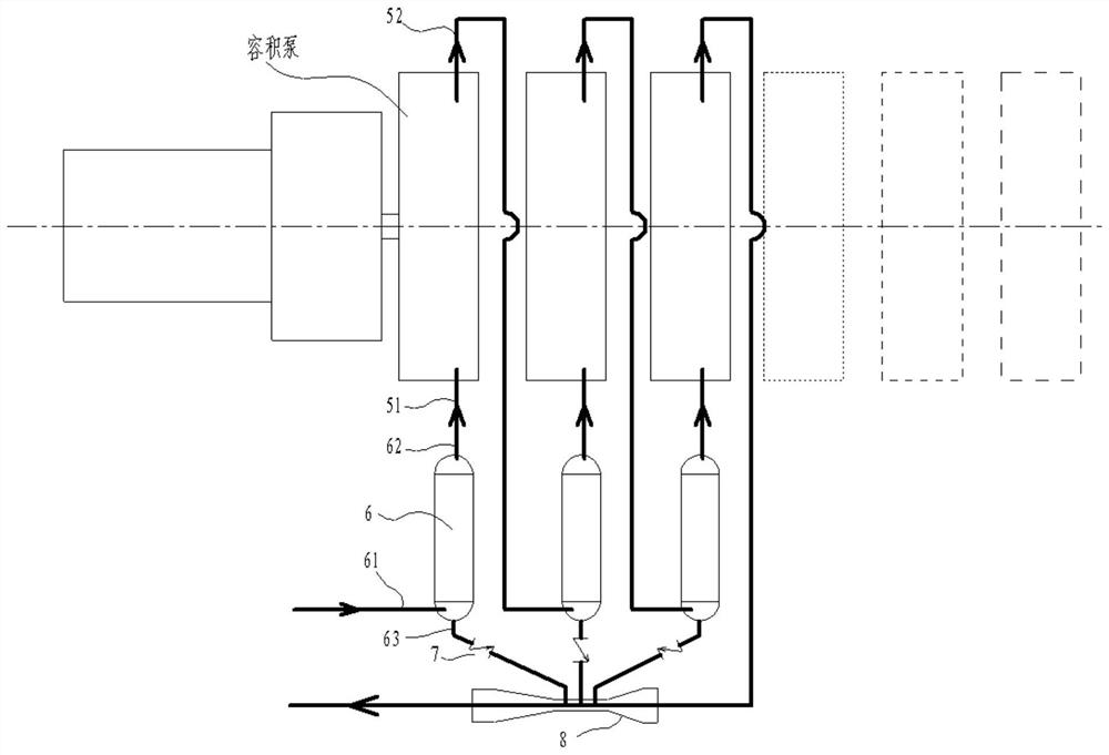
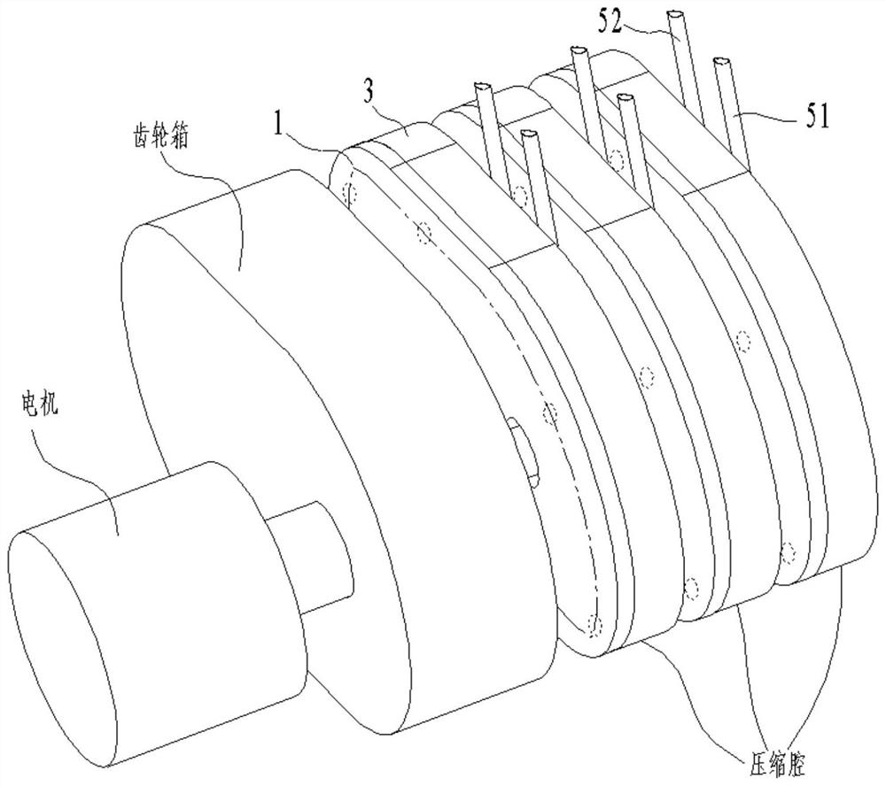
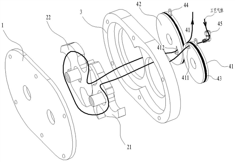
[0037] Such as figure 1 , 7 As shown, a gas-liquid mixing conveying device with a three-claw rotor includes a positive displacement pump, a heat exchanger 6 and a venturi tube 8, and the heat exchanger 6 includes an air inlet 61, an air outlet 62 and a condensate outlet 63, The air inlet 61 is the medium inlet, the air outlet 62 is connected to the inlet of the positive displacement pump, the outlet of the positive displacement pump is connected to the inlet ...


PUM


Abstract

The invention discloses a gas-liquid mixing and conveying device with a three-jaw rotor. The device comprises a positive displacement pump, a heat exchanger and a Venturi tube, wherein the heat exchanger comprises a gas inlet, a gas outlet and a condensate outlet, the gas inlet serves as a medium inlet, the gas outlet is connected to a positive displacement pump inlet, the positive displacement pump outlet is connected to an inlet of the Venturi tube, and the condensate outlet is connected to a Venturi throat tube. The positive displacement pump comprises several compression stages, each compression stage comprises a partition plate, a first rotor, a second rotor, a pump cover, a gas inlet pipe and a gas outlet pipe, the two rotors are meshed with each other in the pump cover, and a gas inlet and a gas outlet of each compression stage forms a series or parallel relationship through the gas inlet pipe and the gas outlet pipe. When connected in series, heat exchangers are arranged amongthe compression stages and a first-stage inlet, and a final-stage compression-stage gas outlet pipe is connected to an inlet of the Venturi tube; and when in parallel, heat exchangers are arranged ora common heat exchanger is arranged before the several compression stages, and gas outlet of the several compression stages are summarized and then is connected to the inlet of the Venturi tube.

Description

technical field [0001] The invention relates to the field of gas-liquid conveying devices, in particular to a gas-liquid mixing conveying device with a three-claw rotor. Background technique [0002] In many chemical treatment processes, it is often encountered that the gas-liquid mixture is transported or although the original medium is in the gas phase, the liquid phase is precipitated when the pressure is slightly increased. The gas-liquid two-phase state of most media is related to pressure and temperature, such as water, Water vapor under normal pressure becomes liquid when it cools below 100 degrees, and is separated from the gas. Similarly, isothermally compressing water vapor at 150 degrees can still force it to change into a liquid state. Therefore, if the process medium directly enters the volume Compression is carried out in the pump, and the condensables in it may be precipitated from the gas phase, and the diaphragm type positive displacement pump with low remov...

Claims


Application Information

Patent Timeline
Patent Type & Authority Applications(China)
IPC IPC(8): F04C18/18F04C23/02F04C29/04F04F5/24F04F5/54
CPCF04C18/084F04C18/18F04C23/02F04C29/04F04F5/24F04F5/54
Inventor 李杰
Owner YUEQING RUIYI ECONOMIC INFORMATION CONSULTING CO LTD
Why Eureka
Try Eureka