
Control method and system for static reactive power compensation of power grid

A static var compensation and control method technology, applied in reactive power compensation, reactive power adjustment/elimination/compensation, electrical components, etc., can solve problems such as reducing the static var compensation efficiency of the compensation circuit and affecting the normal operation of the compensation circuit , to achieve the effect of improving the stability of work and the reliability of static var compensation

Inactive Publication Date: 2021-11-02
SHANGHAI YINGTONG ELECTRIC
View PDF0 Cites 0 Cited by
  • Summary
  • Abstract
  • Description
  • Claims
  • Application Information

AI Technical Summary

Problems solved by technology

Although the compensation circuit can effectively reduce reactive power, the resistance contained in the RC circuit will generate heat during the static var compensation process. If the heat is not dissipated in time but accumulated in the compensation circuit, it will Seriously affect the normal operation of the compensation circuit, thereby reducing the static var compensation efficiency of the compensation circuit

Method used


Image

  • Control method and system for static reactive power compensation of power grid
  • Control method and system for static reactive power compensation of power grid
  • Control method and system for static reactive power compensation of power grid

Examples


Embodiment Construction

[0055] The following will clearly and completely describe the technical solutions in the embodiments of the present invention with reference to the accompanying drawings in the embodiments of the present invention. Obviously, the described embodiments are only some, not all, embodiments of the present invention. Based on the embodiments of the present invention, all other embodiments obtained by persons of ordinary skill in the art without creative efforts fall within the protection scope of the present invention.

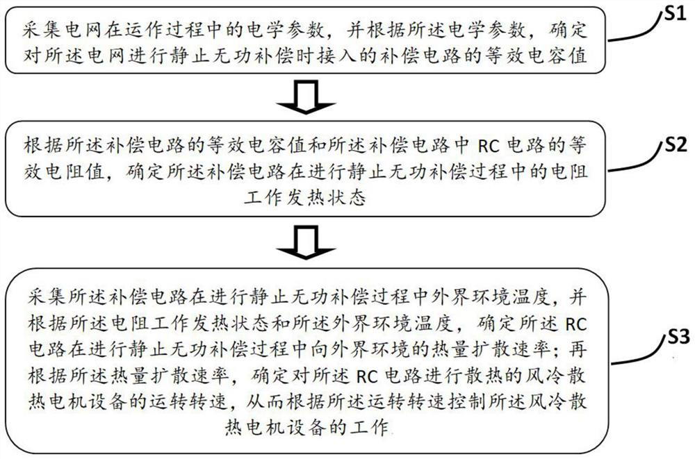
[0056] refer to figure 1 , is a schematic flowchart of a control method for grid static var compensation provided by an embodiment of the present invention. The control method for static var compensation of the power grid includes the following steps:

[0057] Step S1, collecting electrical parameters of the power grid during operation, and determining the equivalent capacitance value of the compensation circuit connected to the power grid when static var compensa...


PUM


Abstract

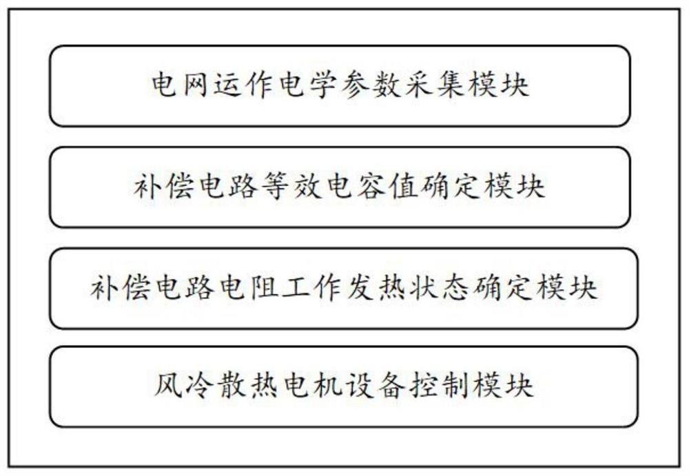
The invention provides a control method and system for static reactive power compensation of a power grid. The method comprises the steps of determining an equivalent capacitance value of a compensation circuit which is connected when the static reactive power compensation is carried out on the power grid according to the operation electrical parameters of the power grid, then determining the working heating state of a resistor of the compensation circuit in the static reactive power compensation process, determining a heat diffusion rate of an RC circuit of the compensation circuit and an external environment by combining the temperature of the external environment, and finally determining the actual fan blade rotating speed of a cooling fan for cooling the RC circuit. Therefore, the heat generated by the corresponding RC circuit in the static reactive compensation process of the compensation circuit can be timely dissipated, the working stability and the static reactive compensation reliability of the compensation circuit are improved, and the efficient and stable operation of the power grid is realized.

Description

technical field [0001] The invention relates to the technical field of smart grid management, in particular to a control method and system for grid static reactive power compensation. Background technique [0002] During the operation of the AC grid, corresponding reactive power will inevitably be generated. This reactive power will not only cause a large amount of ineffective heat to be generated during the operation of the AC grid and reduce the power transmission efficiency of the AC grid, but also increase the workload. In order to reduce the reactive power generated by the AC grid, in the prior art, a compensation circuit including an RC circuit is connected to the AC grid to perform static var compensation on the AC grid. Although the compensation circuit can effectively reduce reactive power, the resistance contained in the RC circuit will generate heat during the static var compensation process. If the heat is not dissipated in time but accumulated in the compensati...

Claims


Application Information

Patent Timeline
Patent Type & Authority Applications(China)
IPC IPC(8): H02J3/18H02J3/01H05K7/20
CPCH02J3/18H02J3/01H05K7/20136Y02E40/30Y02E40/40
Inventor 刘幼林曾广磊周盼
Owner SHANGHAI YINGTONG ELECTRIC
Learn More