Power generation unit and energy output equipment

A technology of energy output and power generation unit, which is applied in the field of power system to achieve the effect of stable operation

Inactive Publication Date: 2014-06-18
SIEMENS AG
View PDF4 Cites 0 Cited by
  • Summary
  • Abstract
  • Description
  • Claims
  • Application Information

AI Technical Summary

Problems solved by technology

Therefore, although the power generation unit 200 is powered by intermittent renewable energy, it has similar output characteristics to conventional energy power generation units.

Method used


Image

  • Power generation unit and energy output equipment
  • Power generation unit and energy output equipment
  • Power generation unit and energy output equipment

Examples


Embodiment Construction

[0037] In the following, various embodiments of the present invention will be described in detail with reference to the accompanying drawings.

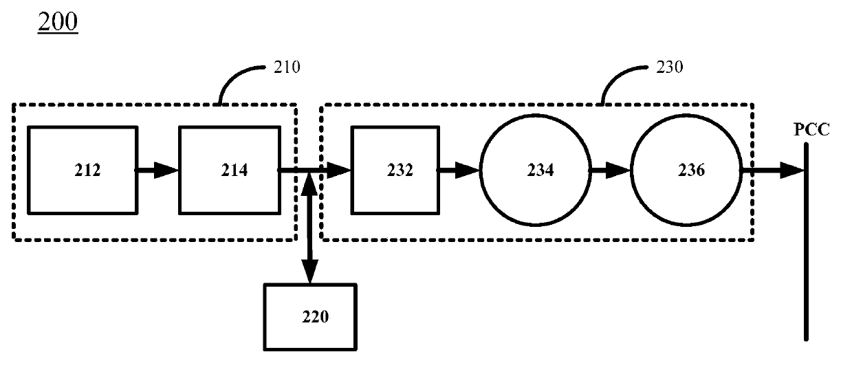
[0038] image 3 A power generation unit 300 is shown in one embodiment according to the invention. The power generation unit 300 is used to convert intermittent energy or renewable energy or intermittent renewable energy into electrical energy for the power grid. The grid can be a microgrid or a backbone grid.

[0039] Such as image 3 As shown, the power generation unit 300 includes: an energy input module 310 for capturing one or more intermittent energy sources and outputting electrical energy converted from the captured intermittent energy sources; The terminals are connected to store the electric energy output by the energy input module 310; the energy output module 330 includes a first energy output module 332 and a bidirectional converter 334 connected in parallel with the first energy output module 332 . The input end of t...


PUM


Abstract

The invention discloses a power generation unit and energy output equipment and relates to the power generation unit. The power generation unit comprises an energy input module, an energy storing module and an energy output module, wherein the energy input module is used for capturing intermittent energy and outputting electric energy converted from the captured intermittent energy; the energy storing module is connected with the output end of the energy input module and is used for storing the electric energy output by the energy input module; the energy output module comprises a first energy output module and a bidirectional current transformer which are connected in parallel; the first energy output module is used for receiving the electric energy from the energy input module and / or the electric energy stored by the energy storing module and outputting the electric energy to a public link point; the bidirectional current transformer is used for outputting the electric energy from the energy input module and / or the electric energy stored by the energy storing module to the public link point or transmitting the electric energy from the public link point to the energy storing module. The power generation unit can work in multiple modes and can flexibly run in different running modes according to the grid state, the environment state and the state of the power generation unit.

Description

technical field [0001] The invention relates to a power system, in particular to a power generation unit and an energy output device. Background technique [0002] At present, a microgrid can refer to a small power generation, distribution, and consumption system composed of one or more parts such as distributed power generation units, energy conversion devices, monitoring devices, protection devices, and related loads. The so-called small is smaller than the scale of the main power grid. The microgrid can run in parallel / parallel / grid-connected with the external power grid (such as the main power grid, etc.), or it can run independently. Generally speaking, a microgrid is an autonomous system capable of self-control, self-protection, and self-management. [0003] The power generation units in the microgrid generally have multiple types such as the first energy generation unit and the second energy generation unit. The first energy generating unit is driven by such as ren...

Claims


Application Information

Patent Timeline
Patent Type & Authority Applications(China)
IPC IPC(8): H02J3/00H02J3/28H02J3/38
Inventor 廖华张京伟李晶马琳
Owner SIEMENS AG
Why Eureka
Try Eureka