Brake device for vehicle

A technology for braking devices and vehicles, which is applied to braking transmission devices, braking action starting devices, brakes, etc., can solve problems such as increased cost and weight, adverse effects of peripheral electrical components, etc., to minimize pulsation amplitude, realize pedal Simulator function, the effect of ensuring braking performance

Active Publication Date: 2020-10-30
HYUNDAI MOBIS CO LTD
View PDF7 Cites 0 Cited by
  • Summary
  • Abstract
  • Description
  • Claims
  • Application Information

AI Technical Summary

Problems solved by technology

However, an increase in the number of pumps and an increase in motor capacity may increase cost and weight, and adversely affect peripheral electrical components such as ECUs

Method used


Image

  • Brake device for vehicle
  • Brake device for vehicle
  • Brake device for vehicle

Examples


Embodiment Construction

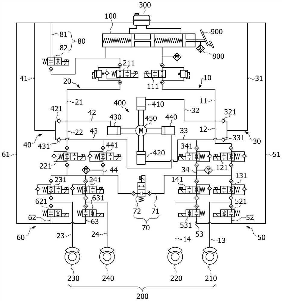
[0033] Hereinafter, a brake device for a vehicle will be described below through various examples of embodiments with reference to the accompanying drawings. It should be noted that the drawings are not to precise scale, and the thickness of lines or the size of components may be exaggerated for descriptive convenience and clarity only. It should be noted that the drawings are not to precise scale, and the thickness of lines or the size of components may be exaggerated for descriptive convenience and clarity only. Accordingly, terms should be defined in light of the entire disclosure set forth herein.

[0034] figure 1 is a diagram schematically showing a representation of an example of a braking device for a vehicle according to an embodiment of the present disclosure. refer to figure 1 , the brake device for a vehicle according to an embodiment of the present disclosure includes a first flow path unit 10 to an eighth flow path unit 80 .

[0035] The first flow path unit ...


PUM


Abstract

The invention relates to a brake device for a vehicle. The brake device includes a first flow path unit guiding a braking hydraulic pressure by connecting some of wheel cylinder units and a master cylinder unit; a second flow path unit guiding a braking hydraulic pressure by connecting the others of the wheel cylinder units and the master cylinder unit; a third flow path unit connecting a reservoir and pump units, and connected with the first flow path unit; a fourth flow path unit connecting the reservoir and the pump units, and connected with the second flow path unit; a fifth flow path unitconnecting the reservoir and the first flow path unit; a sixth flow path unit connecting the reservoir and the second flow path unit; a seventh flow path unit selectively connecting the first and second flow path units; and an eighth flow path unit connecting the second flow path unit and the reservoir.

Description

[0001] Cross References to Related Applications [0002] This application claims priority and benefit from Korean Patent Application No. 10-2019-0049126 filed on April 26, 2019, which is hereby incorporated by reference for all purposes as set forth herein. technical field [0003] Exemplary embodiments of the present disclosure relate to a braking device for a vehicle, and more particularly, to a braking device capable of improving pump utilization efficiency, minimizing pulsation amplitude, realizing a pedal simulator function, and ensuring desired braking performance. vehicle brakes. Background technique [0004] Recently, hybrid vehicles, fuel cell vehicles, electric vehicles, etc. have been actively developed to improve fuel efficiency and reduce exhaust gas. These vehicles necessarily require braking devices, ie braking devices for slowing down or stopping a moving vehicle. [0005] Braking devices of conventional electronically controlled braking systems include vac...

Claims


Application Information

Patent Timeline
Patent Type & Authority Applications(China)
IPC IPC(8): B60T13/14B60T8/40
CPCB60T13/14B60T13/141B60T8/409B60T7/042B60T13/166B60T13/662B60T13/686B60T17/06B60T13/142B60T13/147B60T17/04B60T2220/04B60T8/4013B60T8/4068B60T8/4022
Inventor 安成基朴成俊
Owner HYUNDAI MOBIS CO LTD
Why Eureka
Try Eureka