
Nanometer material mixing device and using method thereof

A nanomaterial and mixing device technology, applied in mixers, nanotechnology, chemical instruments and methods, etc., can solve the problems of low mixing efficiency of nanomaterials, poor force on nanomaterials, difficult stirring effect, etc., and improve mixing uniformity. and mixing efficiency, improving mixing effect, improving uniformity and mixing efficiency

Inactive Publication Date: 2020-10-30
绍兴市梓昂新材料有限公司
View PDF1 Cites 1 Cited by
  • Summary
  • Abstract
  • Description
  • Claims
  • Application Information

AI Technical Summary

Problems solved by technology

[0003] After retrieval, the utility model patent with the publication number CN210584732U discloses a nanomaterial mixing device. The nanomaterial mixing device includes a base, and four mounting seats are fixedly connected to the base, and each mounting seat is rotatably connected to a Linkage rods, each linkage rod is provided with a bearing plate, and each linkage rod is rotatably connected to the object bearing plate, and two of the mounting seats are rotatably connected with deflection screws, and the base is provided with a deflection mechanism that drives the deflection of the bearing plate, There are two brackets fixedly connected to the object bearing plate, and the cylinder body is connected with rotation between the two brackets. A feed pipe and a discharge pipe are respectively fixedly connected to the two supports. The feed pipe and the discharge pipe They are respectively connected to the cylinder by rotation. A rack is provided on the outer wall of the cylinder. A stirring motor is fixedly connected to the material bearing plate. A bevel gear is provided on the rotating shaft of the agitating motor. The bevel gear meshes with the rack for further There is a feeding mechanism on the material tube, which can improve the mixing method of nanomaterials and improve the mixing uniformity of nanomaterials; the device drives the cylinder to deflect and rotate through the set deflection mechanism and stirring motor, so as to achieve the mixing of nanomaterials. effect, but the nanomaterials inside the cylinder are under poor force, and it is difficult to receive a good stirring effect, so not only the mixing efficiency of nanomaterials is low, but also the mixing uniformity also has certain shortcomings.

Method used


Image

  • Nanometer material mixing device and using method thereof
  • Nanometer material mixing device and using method thereof
  • Nanometer material mixing device and using method thereof

Examples


Embodiment 1

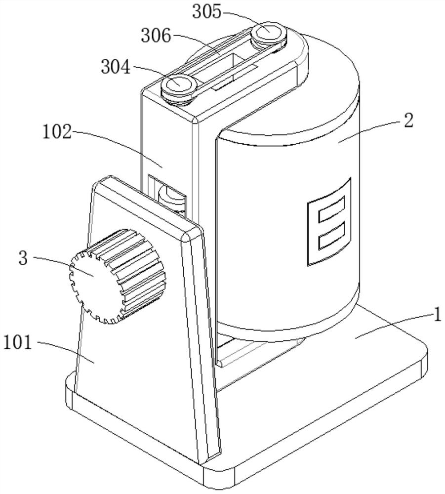
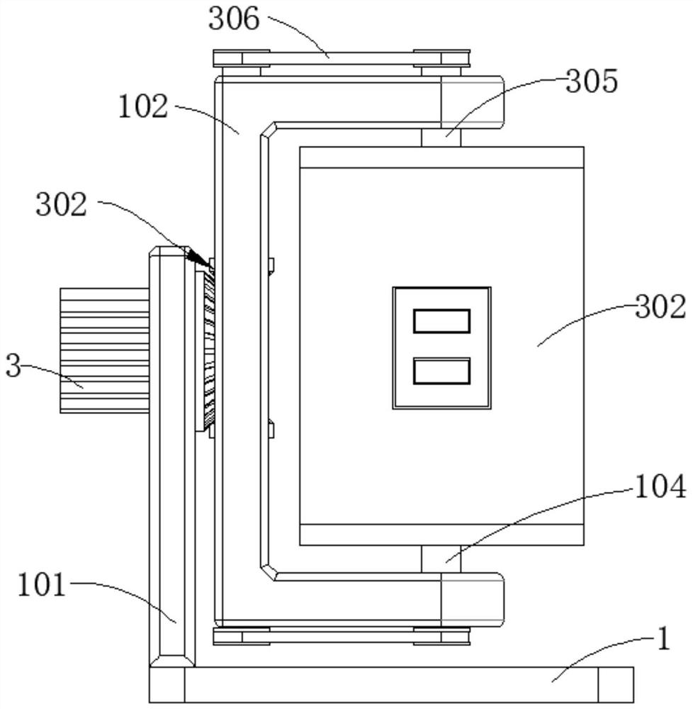
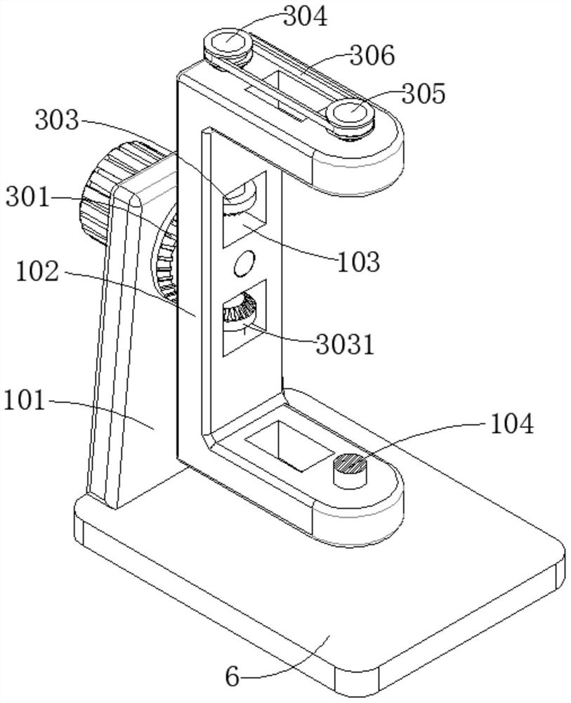
[0041] refer to Figure 1-10 , a nano-material mixing device, including a base 1 and a cylinder 2, a first support plate 101 is connected to the top wall of the base 1, a drive motor 3 is connected to the outer wall of the first support plate 101, and the output end of the drive motor 3 passes through the second A support plate 101 is connected with the active bevel gear 301, the outer wall of the active bevel gear 301 is connected with a U-shaped support frame 102, the cylinder body 2 is rotatably connected to the inner wall of the U-shaped support frame 102, and the outer wall of the U-shaped support frame 102 is dug with a concave Groove 103, the transmission assembly 302 is connected inside the groove 103, the output end of the transmission assembly 302 passes through the U-shaped support frame 102 and is connected with the second rotating shaft 305 and the third rotating shaft 104 respectively, and the second rotating shaft 305 is far away from the transmission assembly 30...

Embodiment 2

[0050] refer to Figure 4-10 , a nanomaterial mixing device, which is basically the same as that of Embodiment 1. Furthermore, the stirring assembly 503 includes a sliding sleeve 504 and a third stirring rod 505. The sliding sleeve 504 is slidably connected to the outer wall of the third rotating shaft 104, and the third The stirring rod 505 is rotatably connected to the outer wall of the sliding sleeve 504, and the end of the third stirring rod 505 away from the sliding sleeve 504 is connected to the second support plate 6 through the slider 506, and a Reciprocating assembly 601.

[0051] The sliding sleeve 504 , the third stirring rod 505 , the slider 506 and the reciprocating assembly 601 are symmetrically arranged in two groups along the second support plate 6 .

[0052] The reciprocating assembly 601 includes a first rotating disk 602, a second rotating disk 603 and a connecting rod 604, the first rotating disk 602 and the second rotating disk 603, the first rotating dis...


PUM


Abstract

The invention discloses a nanometer material mixing device. The device comprises a base and a cylinder body, wherein a first supporting plate is connected to the top wall of the base; the outer wall of the first supporting plate is connected with a driving motor; the output end of the driving motor penetrates through the first supporting plate and is then connected with a driving bevel gear; the outer wall of the driving bevel gear is connected with a U-shaped support frame; a transmission assembly is connected to the U-shaped support frame; the output end of the transmission assembly penetrates through the U-shaped support frame and is then connected with the cylinder body; the outer wall of a third rotating shaft is connected with a transmission gear set; the output end of the transmission gear set is connected with a first stirring rod and a second stirring rod separately; the outer wall of the third rotating shaft is connected with a stirring assembly; and the end, away from the third rotating shaft, of the stirring assembly is connected with a brush plate. The mixing device is novel in structure and convenient to use; through the arrangement of a driving assembly, the transmission assembly and the stirring assembly, the mixing uniformity and the mixing efficiency of nanometer materials can be effectively improved; and meanwhile, the interior of the cylinder body can be conveniently cleaned in a later period.

Description

technical field [0001] The invention relates to the technical field of nanomaterial processing equipment, in particular to a nanomaterial mixing device and a method for using the same. Background technique [0002] Nanoscale structure materials are referred to as nanomaterials for short. In a broad sense, it is a general term for ultrafine particle materials with at least one dimension in the nanoscale range in three-dimensional space; according to the definition adopted by the European Commission on October 18, 2011, nanomaterials are a kind of basic particle A natural or artificial material in the form of a powder or agglomerate, one or more of which has one or more dimensions between 1 nanometer and 100 nanometers, and the total number of this basic particle is in the total number of all particles in the entire material Accounting for more than 50%; before nanomaterials are formed, various types of nanomaterials need to be mixed in proportion, and the mixing uniformity of...

Claims


Application Information

Patent Timeline
IPC IPC(8): B01F7/16B01F7/24B01F7/26B01F15/00B82Y40/00B01F27/93
CPCB82Y40/00B01F27/85B01F27/92B01F27/93B01F35/121
Inventor 朱盼盼王成金雅娣
Owner 绍兴市梓昂新材料有限公司
Learn More