
Self-air-entraining ternary hydraulic jump stilling basin

A technology of stilling pool and stilling pool floor, which is applied in the directions of hydropower generation, hydropower station, water conservancy project, etc., can solve the problems of increasing project investment, cavitation damage of stilling pool floor and side wall, and endangering structural safety, etc.

Active Publication Date: 2020-10-23
CHINA POWER CONSRTUCTION GRP GUIYANG SURVEY & DESIGN INST CO LTD +1
View PDF5 Cites 1 Cited by
  • Summary
  • Abstract
  • Description
  • Claims
  • Application Information

AI Technical Summary

Problems solved by technology

However, when the conventional stilling pool structure is adopted, in order to form a complete binary hydraulic jump, the length of the stilling pool is often longer and the pool depth is also deeper, resulting in a large amount of earthwork excavation and concrete pouring, which increases the project investment
In addition, the flow velocity of the water discharged from the chute to the head of the stilling basin is the highest. It is generally believed that when the flow velocity of the discharged water is greater than 35m / s, it is easy to cause cavitation damage to the bottom plate and side walls of the stilling basin, endangering the safety of the structure. Pools often do not have special aeration and corrosion reduction measures

Method used


Image

  • Self-air-entraining ternary hydraulic jump stilling basin
  • Self-air-entraining ternary hydraulic jump stilling basin
  • Self-air-entraining ternary hydraulic jump stilling basin

Examples


Embodiment Construction

[0025] The present invention will be further described in detail below in conjunction with the accompanying drawings and embodiments.

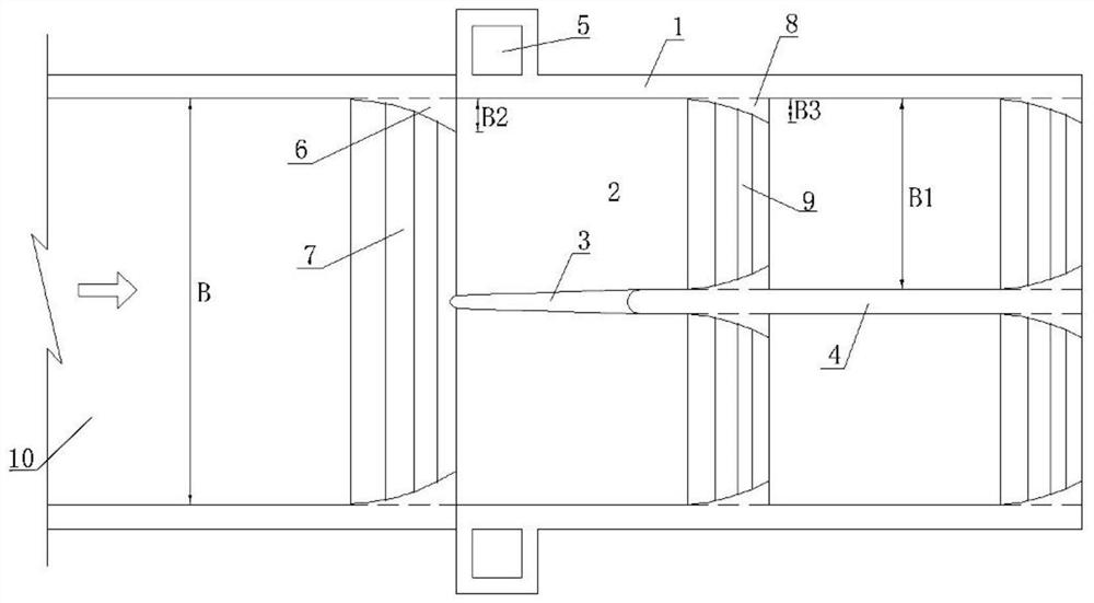
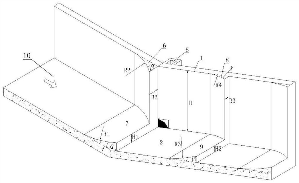
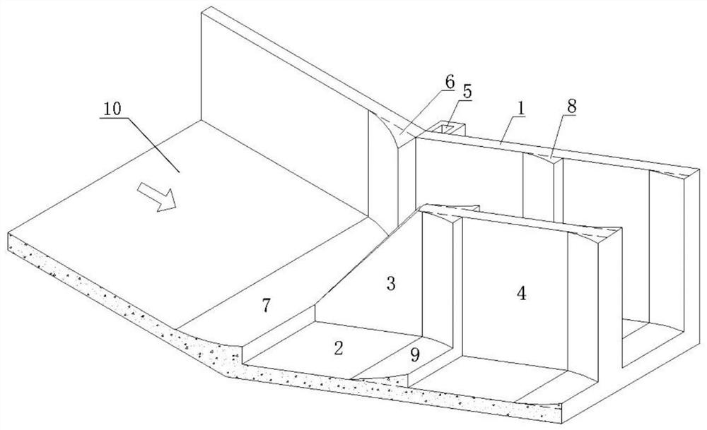
[0026] Such as figure 1 , figure 2 , image 3 As shown, the present invention includes the following components: stilling pool side wall 1, stilling pool bottom plate 2, diversion pier 3, middle partition wall 4, ventilation shaft 5, anti-arc paste angle 6, anti-arc drop sill 7, lateral paste Angle 8, stilling ridge 9, chute 10.

[0027] The specific implementation is as follows:

[0028] The side wall 1 of the stilling pool and the bottom plate 2 of the stilling pool are respectively connected with the side wall and bottom plate of the upstream chute 10, and the middle part of the stilling pool is provided with a diversion pier 3 and a middle partition wall 4, and the middle partition wall 4 is connected to the side wall 1 of the stilling pool The width of B1 is B1, and the width of B1 is determined according to the actual situation. Whe...


PUM


Abstract

The invention discloses a self-air-entraining ternary hydraulic jump stilling basin. The stilling basin is provided with reverse-arc fillets and a reverse-arc step-down floor on a junction of a discharge chute and the stilling basin; two sides of a head side wall of the stilling basin are independently provided with an aeration shaft; the middle of the stilling basin is provided with a flow splitting pier and a middle partition wall; the middle part and the tail parts of the side wall and the middle partition wall of the stilling basin are independently provided with a lateral fillet; the middle and the tail of the bottom plate of the stilling basin are independently provided with a stilling ridge; therefore, binary hydraulic jump of a conventional stilling basin is transformed into ternary hydraulic jump, a strong friction and mixing function of a water body in the hydraulic jump can be enhanced, the energy dissipation power of the stilling basin is improved, the length and the depthof the conventional stilling basin can be reduced, the engineering quantity of the stilling basin is lowered, and engineering investment is lowered. Due to the arrangement of the shaft, the bottom ofthe stilling basin can be subjected to self air entraining, under a turbulent fluctuation function of a high-speed water flow, a great quantity of air is forced to be mixed into the water flow so as to form a gas and water two-phase mixing phenomenon, the air-entraining concentration of the water body is guaranteed, the bottom plate and the side wall of the stilling basin are protected from cavitation destruction, and the safety of a structure is guaranteed.

Description

technical field [0001] The invention relates to a self-aeration three-element hydraulic stilling pool, which belongs to the technical field of water conservancy and hydropower engineering. Background technique [0002] In water conservancy and hydropower engineering, for the high-speed discharge flow, in order to reduce the erosion of the natural channel behind the dam and ensure the safety of the main body of the dam, three energy dissipation methods are mainly used to dissipate the energy of the discharge flow: deflecting flow energy dissipation, bottom flow dissipation energy, surface flow energy dissipation. When the topographical conditions of the energy dissipation area of ​​the discharge flow are limited, the erosion resistance of the riverbank and the river bed is poor, and the downstream water level is shallow and the water level varies greatly, the energy dissipation method of the discharge flow generally adopts the bottom flow energy dissipation method. Underflow...

Claims


Application Information

Patent Timeline
IPC IPC(8): E02B8/06E02B8/00E02B9/06
CPCE02B8/06E02B8/00E02B9/06Y02E10/20
Inventor 王瑞
Owner CHINA POWER CONSRTUCTION GRP GUIYANG SURVEY & DESIGN INST CO LTD
Learn More