
An electromagnetically triggered frictional pressure release device

A release device and electromagnetic triggering technology, which is applied to the docking device of space navigation vehicle, transportation and packaging, and space navigation equipment, etc. , The effect of short power-on time and simple mechanism design

Active Publication Date: 2021-11-16
HARBIN INST OF TECH
View PDF7 Cites 0 Cited by
  • Summary
  • Abstract
  • Description
  • Claims
  • Application Information

AI Technical Summary

Problems solved by technology

Although the traditional pyrotechnic trigger method is reliable in separation and short in action time, it often has a large impact and is not repeatable. After triggering, a lot of harmful gas is generated, and the attached ignition system is not conducive to the miniaturization of the device.
Nowadays, many non-pyrotechnic compression release devices have partially overcome the shortcomings of pyrotechnic triggering, but they have brought new problems, such as long actuation time, heat sensitivity, complex mechanism, large space occupation, small load, etc.

Method used


Image

  • An electromagnetically triggered frictional pressure release device
  • An electromagnetically triggered frictional pressure release device
  • An electromagnetically triggered frictional pressure release device

Examples


Embodiment Construction

[0036] It should be noted that, in the case of no conflict, the embodiments of the present invention and the features in the embodiments can be combined with each other.

[0037] The present invention will be described in detail below with reference to the accompanying drawings and examples.

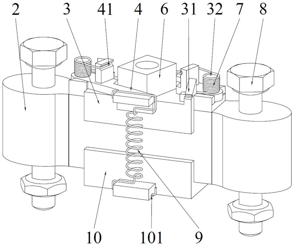
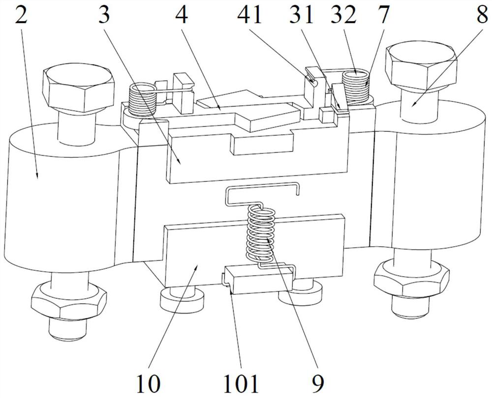
[0038] Such as Figure 1-Figure 9 As shown, an electromagnetically triggered frictional compression release device includes a trigger mechanism, two pull hooks 1, a locking mechanism 2, an upper pressing plate 3, two triggers 4, two torsion springs 7, two tension springs 9, The lower pressing plate 10 and the mounting base 11, the trigger mechanism is installed on the top of the mounting base 11, the upper pressing plate 3, the two triggers 4, the two torsion springs 7, the two tension springs 9 and the lower pressing plate 10 are all set In the mounting seat 11, the locking mechanism 2 is set through the left and right sides of the mounting seat 11, and the two pull hooks 1 are respect...


PUM


Abstract

The invention provides an electromagnetically triggered friction type compression release device, which includes a trigger mechanism, two pull hooks, a locking mechanism, an upper pressure plate, two triggers, two torsion springs, two tension springs, a lower pressure plate and a mounting seat , the trigger mechanism is installed on the top of the mounting seat, the upper pressure plate, trigger, torsion spring, tension spring and lower pressure plate are all arranged in the mounting seat, the locking mechanism passes through the left and right sides of the mounting seat, and the two hooks are respectively connected with the locking mechanism. The left and right ends are connected; in the locked state, the trigger mechanism restricts the rotation of the two triggers, the tension spring pulls the trigger, the trigger is pressed on the upper platen to compress the locking mechanism, and the two hooks are locked; in the unlocked state, the trigger mechanism moves to unlock Two triggers, the torsion spring drives the trigger to rotate, and the tension spring is released from the trigger, releasing the pressing of the trigger on the upper pressure plate, releasing the locking mechanism, and the two hooks are separated. The invention has large bearing capacity, rapid action, repeatable test, insensitive to high and low temperature, and can be applied to various connection and separation occasions.

Description

technical field [0001] The invention belongs to the technical field of compression release devices, in particular to an electromagnetically triggered friction type compression release device. Background technique [0002] With the development of aerospace, aviation, and navigation technologies, the development and application of technologies such as space environment detection, astronomical observation, ocean exploration, space science experiments, and high-altitude target detection has become an urgent need. The function of the compression release device is to ensure reliable locking between the load and the release platform, or between the load and the load during the launch or operation of the equipment; when the system issues a release command, the load can be quickly realized from the release platform. , or the loads are separated from each other. Although the traditional pyrotechnic trigger method is reliable in separation and has a short actuation time, it often has ...

Claims


Application Information

Patent Timeline
Patent Type & Authority Patents(China)
IPC IPC(8): B64G1/64
CPCB64G1/64B64G1/645
Inventor 岳洪浩杨飞姜阳杨逸斐李怀宇
Owner HARBIN INST OF TECH
Learn More