Treatment equipment for medical waste syringes

A technology for processing equipment and syringes, which is applied to hypodermic injection devices, devices introduced into the body, and conveyor objects, etc. It can solve problems such as the inability to form a waste syringe production line, affect the post-processing efficiency of waste syringes, and increase the reuse of waste syringes.

Active Publication Date: 2020-10-23
NANJING HANERSI BIOLOGY TECHNOLOGY CO LTD
View PDF12 Cites 0 Cited by
  • Summary
  • Abstract
  • Description
  • Claims
  • Application Information

AI Technical Summary

Problems solved by technology

[0007] However, the above-mentioned syringe needle separation device still has the following obvious defects in the use process: after the above-mentioned separation device fixes the syringe, it directly separates the syringe by means of guillotine cutting or plug-in, the first point : If the guillotine separation method is used, the choice of the guillotine and the service life need to be considered, and after a long time of use, the guillotine knife may have poor cutting effect, and the plastic material needle barrel and needle connection part will be damaged when the guillotine is cut. After that, the situation that it cannot be completely separated occurs; the second point: if the plug-in method is used, the user's hands cannot be freed, and each separation requires the worker to insert the syringe into the base and fix it before separating, which improves the work efficiency. It is low and cannot be well applied to industrial production. There is no way to form a good production line for separating syringes and needles of waste syringes, which seriously affects the post-processing efficiency of waste syringes and virtually increases waste syringes. Likelihood of being reused

Method used


Image

  • Treatment equipment for medical waste syringes
  • Treatment equipment for medical waste syringes
  • Treatment equipment for medical waste syringes

Examples


Embodiment Construction

[0039] The following will clearly and completely describe the technical solutions in the embodiments of the present invention with reference to the accompanying drawings in the embodiments of the present invention. Obviously, the described embodiments are only some, not all, embodiments of the present invention. Based on the embodiments of the present invention, all other embodiments obtained by persons of ordinary skill in the art without making creative efforts belong to the protection scope of the present invention.

[0040] see Figure 1-16 , the present invention provides a technical solution:

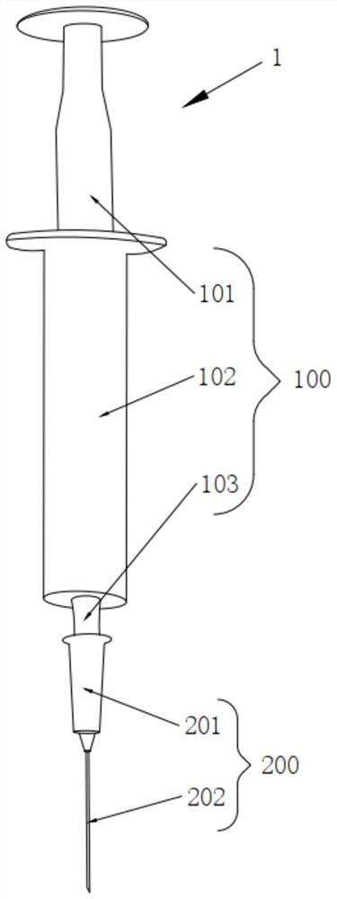
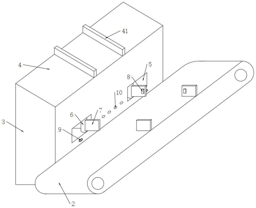
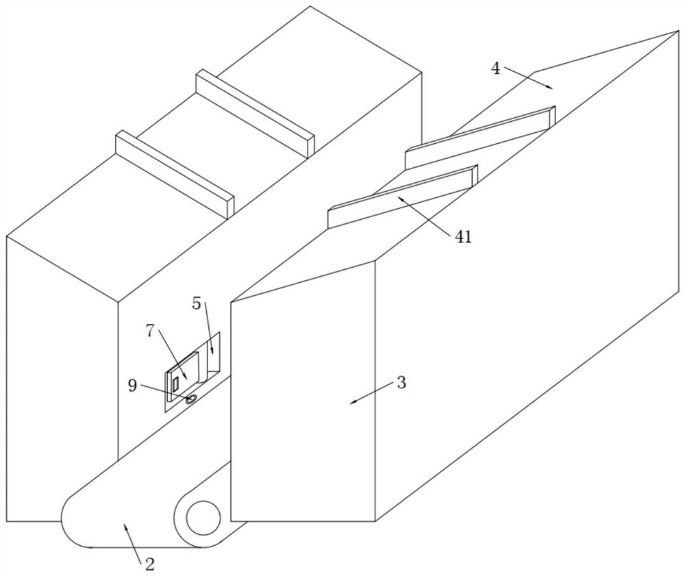
[0041] A processing equipment for medical waste syringes, specifically used for the separation of the syringe part 100 and the needle part 200, including two substrates 3 arranged at intervals, and a sorting conveyor belt 2 arranged between the two substrates 3, the separation Both sides of the belt body of the selection conveyor belt 2 are flexibly connected with the base plate ...


PUM


Abstract

The invention discloses treatment equipment for medical waste syringes. The treatment equipment is particularly used for separating a needle cylinder part from a needle head part and comprises two base plates arranged at an interval and a sorting conveyor belt arranged between the two base plates, two sorting grooves are formed in the side wall of one side, close to the sorting conveyor belt, of each base plate, and treatment plates are vertically arranged at the two ends of the sorting conveyor belt; an overturning groove is formed in each treatment plate, an inserting cylinder is movably arranged in each overturning groove, two arc-shaped clamping plates are separately arranged below each inserting cylinder, and a radian attaching pipe is fixedly connected to the lower portion of a lowering push rod. When garbage environment-friendly treatment is carried out on medical waste syringes, chopping is not needed in the separation process, use of a chopping knife can be avoided, an inserting and pulling mode is not needed any more, both hands of workers can be liberated, the work efficiency for separating the needle cylinder and needle head is greatly improved, and a complete industrial production line can be formed.

Description

technical field [0001] The invention relates to the technical field of environmental protection treatment of medical waste, in particular to a treatment equipment for medical waste syringes. Background technique [0002] Syringes are mainly used in the medical field. The emergence of syringes is an epoch-making revolution in the field of medical appliances. The process of drawing or injecting gas or liquid with a needle is called injection. As attached to the manual figure 1 As shown, the syringe 1 is composed of a syringe part 100 and a needle part 200. The syringe part 100 further includes a liquid pushing rod 101, a liquid cylinder 102 and a butt joint 103. The needle part 200 is composed of a sleeve joint 201 and an injection needle 202. When in use First, it is necessary to socket the sleeve joint 201 on the butt joint 103 for connection and fixation, and then, when the liquid push rod 101 is pulled out, the liquid or gas is sucked from the small hole at the front end ...

Claims


Application Information

Patent Timeline
IPC IPC(8): A61M5/32B65G47/24B65G15/30
CPCA61M5/3205B65G47/24B65G15/30A61M2005/3206
Inventor 孙华东姜锋
Owner NANJING HANERSI BIOLOGY TECHNOLOGY CO LTD
Why Eureka
Try Eureka