
Lens for slowing down myopia deepening and preparation method thereof

A lens and myopia technology, applied to lenses, glasses/goggles, and other household appliances, can solve problems such as uneven film layers and affecting transmittance

Pending Publication Date: 2020-10-20
JIANGSU MINGYUE PHOTOELECTRICS TECH
View PDF2 Cites 17 Cited by
  • Summary
  • Abstract
  • Description
  • Claims
  • Application Information

AI Technical Summary

Problems solved by technology

However, the lens mostly uses injection molding to make different refractive areas on the front surface of the lens. The different refractive areas of the prescription form micro-lenses on the surface, resulting in protrusions or depressions on the surface of the lens, which causes the lens to be coated. In the process of processing, there will be phenomena such as uneven film layer, which will affect the transmittance

Method used


Image

  • Lens for slowing down myopia deepening and preparation method thereof
  • Lens for slowing down myopia deepening and preparation method thereof
  • Lens for slowing down myopia deepening and preparation method thereof

Examples


preparation example Construction

[0038] The preparation method of the above lens specifically comprises the following steps:

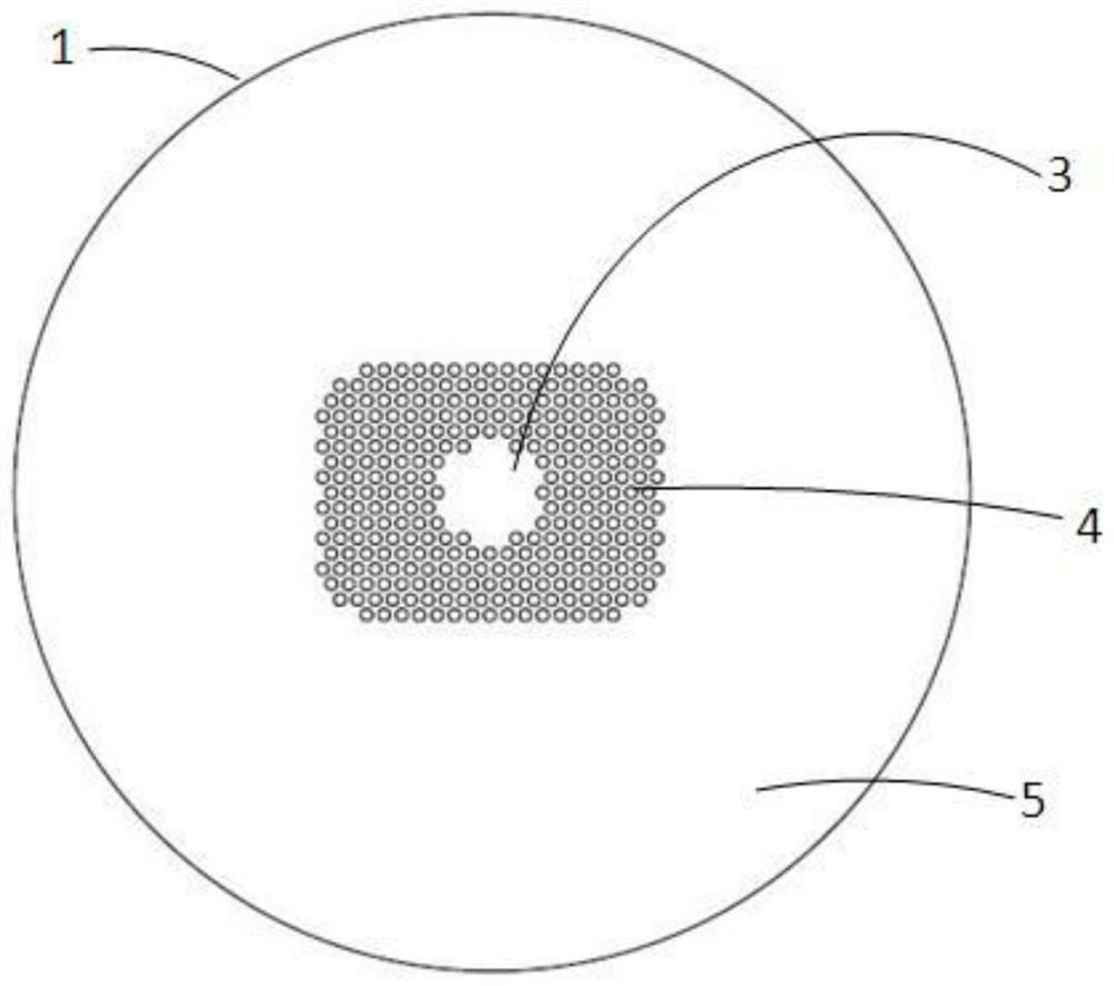
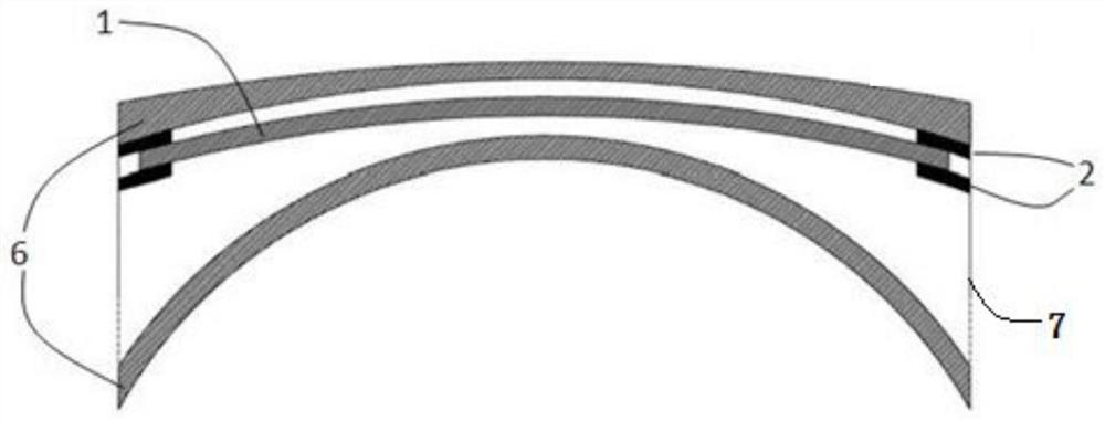
[0039] The first step is to prepare the optical plastic film 1 and prepare the microlens 401 on the surface of the optical plastic film 1 . Among them, the optical plastic film 1 is a hard plastic film, and its material can be PC (polycarbonate), PA (nylon), TAC (triacetyl cellulose), PVA (polyvinyl alcohol), CAB (cellulose acetate butyrate), etc. ), PET (polycarbonate), PMMA (polymethyl methacrylate), PS (polystyrene) and other optical materials.

[0040] Since the size of the microlens 401 produced on the optical plastic film 1 is in the order of millimeters and the depth is in the order of microns, there are several ways to operate such a fine structure, such as thermocompression molding, solvent etching molding, or laser engraving molding.

[0041] The specific method for preparing the microlens 401 on the optical plastic film 1 by thermocompression molding technology is as follo...

Embodiment 1

[0051] A TAC film material with a thickness of 0.20 mm is selected as the optical plastic film 1, and a 1.67 polyurethane material is selected as the lens resin monomer to produce a myopia prevention and control lens that can produce a defocusing effect. The TAC optical plastic film 1 can be processed by thermal embossing or laser precise cutting to process the out-of-focus refraction area 4, and this embodiment selects the method of thermal embossing. The refractive index of the TAC material is 1.475, and the refractive index of the polyurethane resin lens material is 1.67. Select the optimal addition luminosity of +3.50D, and derive the formula R= It can be calculated that the radius of curvature R of the microlens 401 is 55.7 mm. Since the refractive index of the TAC material is smaller than that of the resin monomer, the microlens 401 of the out-of-focus refraction area 4 on the optical plastic film 1 is processed with a concave surface, and the hot-molded template is des...


PUM

PropertyMeasurementUnit
thicknessaaaaaaaaaa
diameteraaaaaaaaaa
refractive indexaaaaaaaaaa

Abstract

The invention relates to a lens for slowing down myopia deepening. The lens comprises two layers of resin monomers and an optical plastic film arranged between the two layers of resin monomers, wherein the optical plastic film sequentially comprises a central flat light area, an out-of-focus refraction area and an external flat light area from inside to outside, and the out-of-focus refraction area is a discontinuous out-of-focus refraction area. According to the invention, the optical plastic film is used for preparing the functional film with the defocusing effect; the functional film is arranged in the middle of the resin lens, so that the lens can still play a role in myopia prevention and control; in addition, tiny bulges do not exist on the surface of the lens, the uniformity of hardening and film coating is not influenced in the subsequent hardening and film coating processes, and the lens is simpler and more thorough to clean when being worn in daily life.

Description

technical field [0001] The invention relates to a lens for slowing myopia deepening and a preparation method thereof, in particular to a myopia prevention and control lens with a defocusing effect and a preparation method thereof, belonging to the technical field of optical resin lenses. Background technique [0002] Myopia is a global social problem and medical problem. In 2015, my country released the first "National Visual Health Report", which pointed out that as of 2012, among the total population over 5 years old in my country, the number of patients with various visual defects was about 500 million. Among them, the total number of patients with myopia is about 450 million. It can be said that almost one out of every three people in China suffers from myopia. At the same time, the "China Compulsory Education Quality Monitoring Report" released by the Basic Education Quality Monitoring Center of the Ministry of Education in 2018 shows that the myopia rate of Chinese tee...

Claims


Application Information

Patent Timeline
Patent Type & Authority Applications(China)
IPC IPC(8): G02C7/06G02C7/02G02B3/00G02B1/04
CPCG02C7/06G02C7/022G02B3/0012G02B3/0031G02B3/0025G02B1/041B29D11/00317B29D11/00009B29D11/0073G02C2202/24
Inventor 谢公兴谢公晚
Owner JIANGSU MINGYUE PHOTOELECTRICS TECH
Learn More