
Valve clip and clipping system thereof

A valve and angle technology, applied in the direction of heart valve, valve annulus, etc., can solve the problems of easy damage to the atrial roof, easy winding of chordae tendineae, large operation space, etc., to reduce the risk of injury, small operation range, simple connection structure. Effect

Pending Publication Date: 2020-10-16
SHANGHAI HANYU MEDICAL TECH CO LTD
View PDF2 Cites 5 Cited by
  • Summary
  • Abstract
  • Description
  • Claims
  • Application Information

AI Technical Summary

Problems solved by technology

We developed and used this patent, and found through actual surgical operations that the device still has too much operating space to capture the valve, and it can only be operated through the ventricle side (the wound from the apex of the heart is still too large), and it is easy to wind the tendon cable, easy to damage the roof of the atrium, and can only capture defects on both sides of the valve at the same time

Method used


Image

  • Valve clip and clipping system thereof
  • Valve clip and clipping system thereof
  • Valve clip and clipping system thereof

Examples


Embodiment approach

[0097] 1) Assembly of push rod 120, delivery pipe 110 and loader 100: as Figure 14 As shown, from the far end of the push rod 120, the push rod is inserted from the proximal end of the delivery tube 110 into the fourth through hole, and then from the far end of the delivery tube 110, the delivery tube 110 is inserted from the proximal end of the loader 100 into the fourth through hole. In the three-way hole;

[0098] 2) Assembly between the base 20 and the fixing ring 60: use the external thread 201 on the base 20 and the internal thread 601 on the fixing ring 60 to realize the screw connection between the base 20 and the fixing ring 60;

[0099] 3) Assembling between the fixing ring 60 and the delivery tube 110: after matching the position of the block 1004 on the extension arm 1001 of the delivery tube 110 with the connecting hole 603 on the fixing ring 60, insert it in the fourth through hole of the delivery tube 110 Push the rod 120, and ensure that the push rod 120 pass...


PUM

PropertyMeasurementUnit
Lengthaaaaaaaaaa
Widthaaaaaaaaaa
Axial lengthaaaaaaaaaa

Abstract

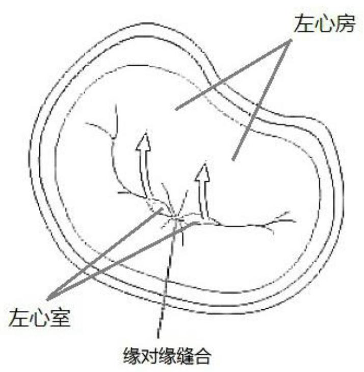
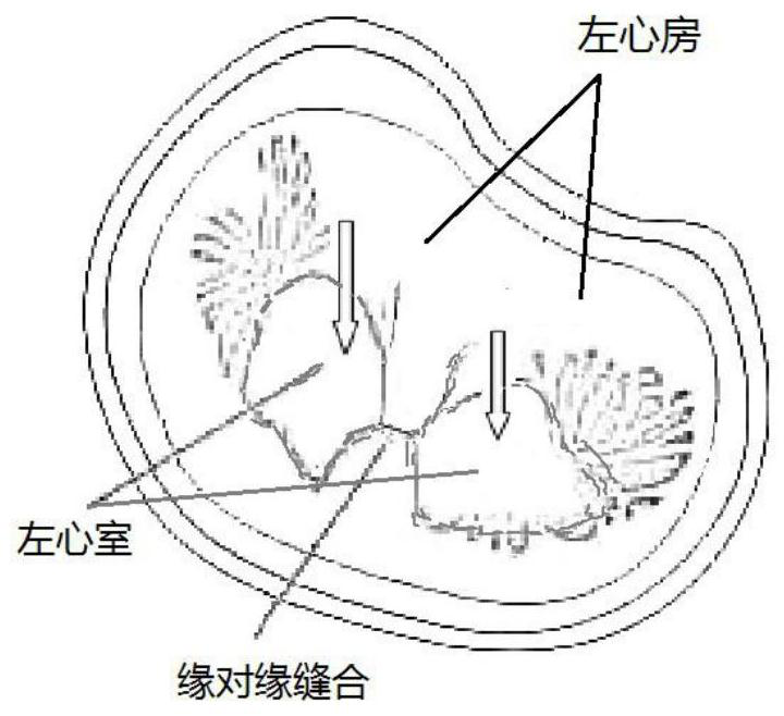
The invention relates to a valve clip and a clipping system thereof. The valve clip can be used for effectively treating MR (Mitral Regurgitation) and TR (Tricuspid Regurgitation) after being implanted into the human body by the clipping system. By using the valve clip, the axial operating space of the valve clip can be shortened, and the operating direction can be changed, so that the capturing and clamping operation can be performed from the other side of the valve (i.e., the atrium side) so as to reduce the injury damage on the atrium and the chordae tendineae in the surgical operation process; the length of the valve clip can be shortened, so that the implanted valve clip is shorter so as to reduce the space of the ventricle side occupied by the valve clip, reduce the injury capable ofbeing caused by the valve clip on the heart tissue, and reduce the thrombus forming risk; in addition, after the clipping system passes through the femoral vein and punctures the septum of the rightatrium and the left atrium, the right atrium and the left atrium are used as a delivery path of the clip; the intercostal incision and cardiac apex puncture are not needed; and the surgical trauma issmaller.

Description

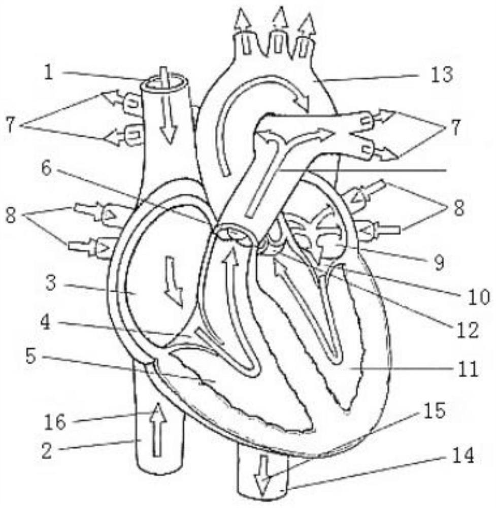
technical field [0001] The invention relates to a valve clamp, in particular to a valve clamp and a clamping system thereof. Background technique [0002] The mitral valve is a two-valve valve attached to the periphery of the left atrioventricular orifice (eg figure 1 As shown), it is connected to the papillary muscle by the chordae, which prevents the blood from the left ventricle from flowing back to the left atrium. [0003] Mitral regurgitation (MR) is due to the organic or functional changes in the mitral valve leaflets and their related structures, resulting in poor anastomosis of the anterior and posterior leaflets of the mitral valve, and blood flow back from the left ventricle to the left atrium, causing a series of pathological Physiological changes. Severe MR can cause left ventricular enlargement, and eventually lead to left ventricular systolic failure and heart failure. At the same time, left atrial pressure also increases due to reflux, which can easily lead...

Claims


Application Information

Patent Timeline
IPC IPC(8): A61F2/24
CPCA61F2/2442A61F2/246A61F2/2466
Inventor 戴宇峰潘炳跃潘文志周达新葛均波
Owner SHANGHAI HANYU MEDICAL TECH CO LTD
Learn More