
Pore diameter tester of copper wire drawing die

A wire drawing die and tester technology, which is applied in wire drawing dies, manufacturing tools, metal processing, etc., can solve problems such as unusable and inability to test the inner wall wear of the wire drawing die, and achieve the effect of reducing the difficulty of operation

Active Publication Date: 2020-10-13
JIANGXI UNIV OF SCI & TECH
View PDF7 Cites 1 Cited by
  • Summary
  • Abstract
  • Description
  • Claims
  • Application Information

AI Technical Summary

Problems solved by technology

[0006] In order to overcome the disadvantages that the wire drawing die with a smaller inner diameter cannot be used and the wear condition of the inner wall of the wire drawing die cannot be tested, the technical problem to be solved by the invention is to provide a wire drawing die with a smaller diameter. The drawing die is tested, and the copper wire drawing die aperture tester can be used to test the wear condition of the inner wall of the drawing die

Method used


Image

  • Pore diameter tester of copper wire drawing die
  • Pore diameter tester of copper wire drawing die
  • Pore diameter tester of copper wire drawing die

Examples


Embodiment 1

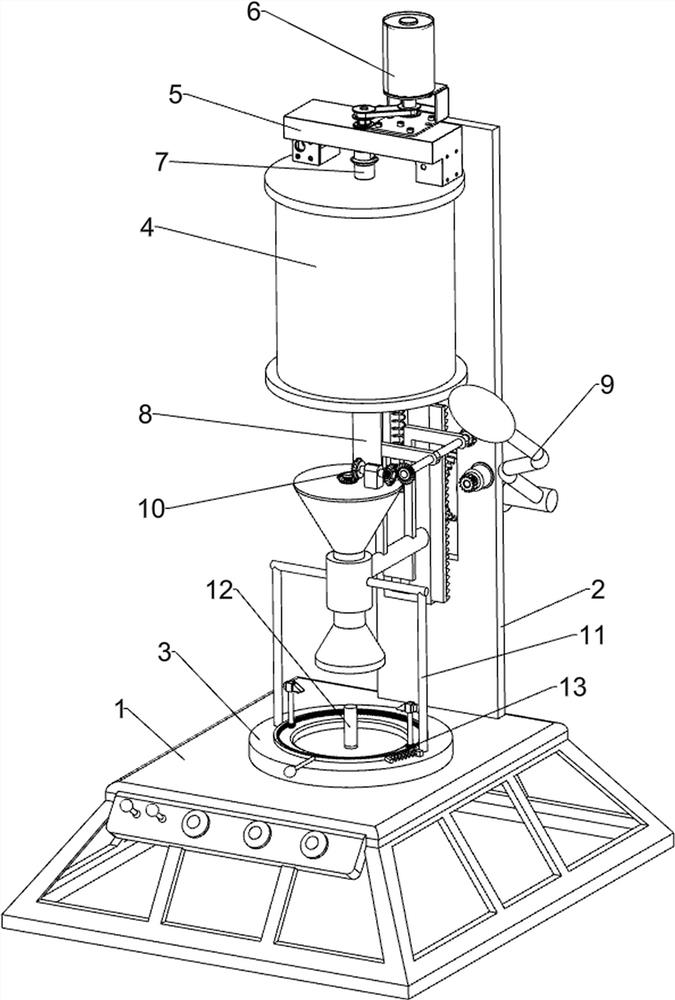
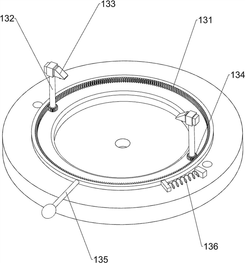
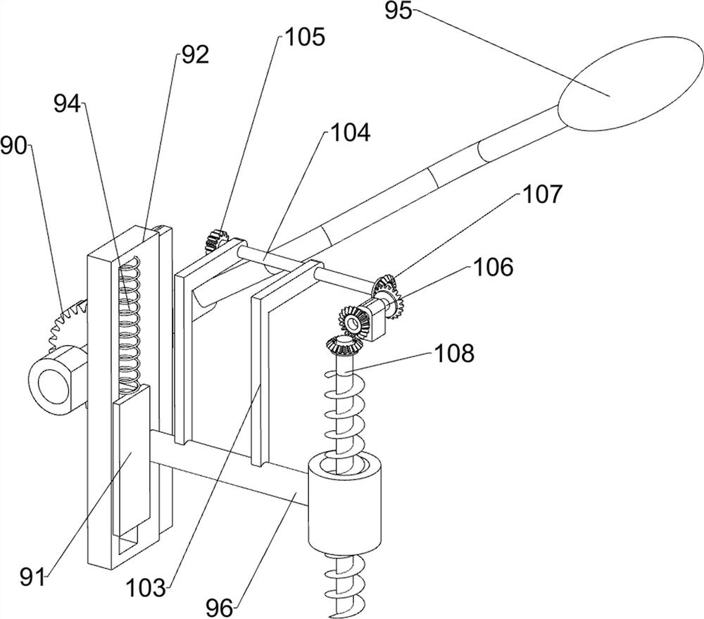
[0024] A copper wire drawing die aperture tester, such as Figure 1-3 As shown, it includes a base 1, a mounting plate 2, a mold placement seat 3, a heat preservation bucket 4, a support 5, a stirring motor 6, a stirring shaft 7, a telescopic material guide tube 8, a closing mechanism 9 and a filling mechanism 10, and the top of the base 1 The rear side is equipped with a mounting plate 2, the middle of the top of the base 1 is connected with a mold placement seat 3, the front side of the top of the mounting plate 2 is connected with a heat preservation bucket 4, the top of the heat preservation bucket 4 is connected with a support 5, and a stirring motor 6 is installed on the support 5 , the output shaft of the stirring motor 6 is connected with the stirring shaft 7, the stirring shaft 7 is located in the heat preservation barrel 4, the telescopic material guide pipe 8 is connected to the bottom of the heat preservation barrel 4, and the closing mechanism 9 is installed in the...

Embodiment 2

[0029] On the basis of Example 1, such as figure 2 As shown, it also includes a guide connecting frame 11 and an extrusion rod 12. A guiding connecting frame 11 is slidably connected between the left and right sides of the mold placement seat 3, and the top of the guiding connecting frame 11 is connected with the connecting rod 96. The guiding connection An extrusion rod 12 is connected in the middle of the inner bottom of the frame 11, and the extrusion rod 12 runs through the mold placement seat 3, and the extrusion rod 12 is slidingly connected with the mold placement seat 3.

[0030] When the wire drawing die is put into the mold placement seat 3, the wire drawing die is set on the outside of the extrusion rod 12. When the connecting rod 96 moves downward, the guide connecting frame 11 drives the extrusion rod 12 to move downward. When the connecting rod 96 moves upward When moving, the extruding rod 12 is driven upward by the guide connecting frame 11, and the upward mov...


PUM


Abstract

The invention relates to a pore diameter tester, in particular to a pore diameter tester of a copper wire drawing die, and aims to provide the pore diameter tester, capable of testing a wire drawing die with a smaller pore diameter and testing the wear condition of the inner wall of the wire drawing die, of the copper wire drawing die. In order to solve the technical problem, the pore diameter tester of the copper wire drawing die is provided and comprises a base, a die placing seat, a thermal insulation barrel, a supporting seat, a stirring motor and a stirring shaft, wherein a mounting plateis connected to the base; the die placing seat is connected to the top of the base; the thermal insulation barrel is connected to the upper part of the mounting plate; the supporting seat is connected to the top of the thermal insulation barrel; the stirring motor is mounted on the supporting seat; and the stirring shaft is connected to an output shaft of the stirring motor. The wire drawing diecan be filled with a vinyl plastic liquid by a closing mechanism and a filling mechanism, plastic rods are formed, and therefore, the specific value of the pore diameter of the wire drawing die can beobtained.

Description

technical field [0001] The invention relates to an aperture tester, in particular to an aperture tester for a copper wire drawing die. Background technique [0002] The wire drawing die refers to a tool that forces the metal to pass through the die under the action of an external force during metal pressure processing, compresses the cross-sectional area of ​​the metal, and obtains the required shape and size of the cross-sectional area. [0003] At present, the test tools for wire drawing dies generally use an outer micrometer tester to test the outer wall of the drawing die. When it is necessary to test the inner diameter of the drawing die, an inner micrometer tester is required. When testing a wire drawing die with a smaller inner diameter, it cannot use, and it is impossible to test the wear of the inner wall of the drawing die. [0004] Therefore, it is necessary to develop a copper wire drawing die aperture tester that can test the smaller wire drawing dies of the ap...

Claims


Application Information

Patent Timeline
IPC IPC(8): B21C51/00B21C3/02
CPCB21C3/02B21C51/00
Inventor 谢小云黄晓东黄学雨卢欣荣
Owner JIANGXI UNIV OF SCI & TECH
Learn More