
Adsorption ball based on water surface floating oil pollution treatment technology

A technology for pollution control and oil slicks on the water surface. It is used in water/sewage treatment, water/sewage treatment equipment, water/sludge/sewage treatment, etc. It can solve the problems of waste, light cannot pass through the oil slick layer, etc., and achieve convenient recycling. Handling, avoiding waste of resources, and ensuring the effect of survival

Inactive Publication Date: 2020-10-09
郭潜
View PDF0 Cites 2 Cited by
  • Summary
  • Abstract
  • Description
  • Claims
  • Application Information

AI Technical Summary

Problems solved by technology

[0005] Aiming at the problems existing in the prior art, the object of the present invention is to provide an adsorption ball based on the oil slick pollution control technology on the water surface, which can guide the light above the oil slick to below the oil slick while absorbing oil, so that the Aquatic plants can carry out normal photosynthesis to ensure the oxygen content in the water, so as to avoid the lack of oxygen in aquatic animals. The oil slick is absorbed by the high oil-absorbing resin and introduced into the inner cavity shell through the guide rod for storage, which can facilitate the oil slick Carry out recycling to avoid waste of resources, and use the optical fiber to guide light to guide the light above the oil slick to below the oil slick, solving the problem that light cannot pass through the oil slick, ensuring the normal survival of aquatic animals and plants, and using Balance the adjustment ball to restore the posture of the adsorption ball, so that when the adsorption ball floats with the waves, the end of the optical fiber on it can still return to the bottom of the oil slick, further ensuring the effective guidance of light

Method used


Image

  • Adsorption ball based on water surface floating oil pollution treatment technology
  • Adsorption ball based on water surface floating oil pollution treatment technology
  • Adsorption ball based on water surface floating oil pollution treatment technology

Examples


Embodiment 1

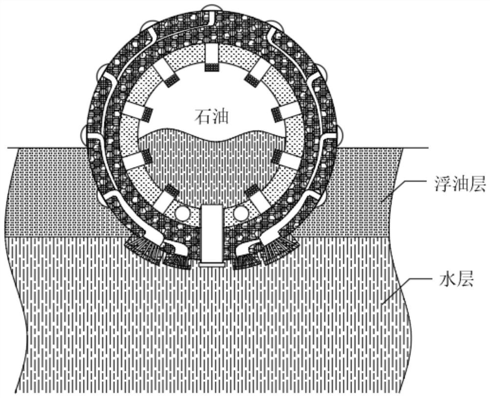
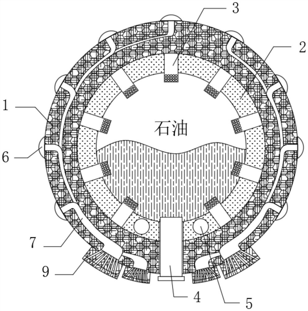
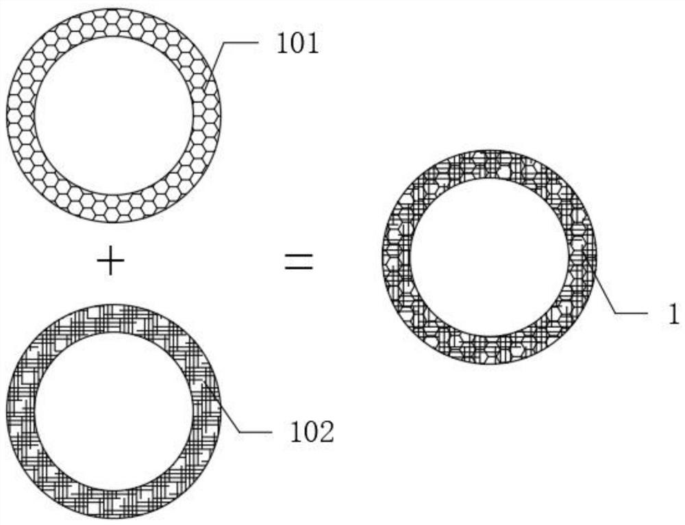
[0043] see Figure 1-6 , an adsorption ball based on water surface oil slick pollution control technology, including 1 absorption layer, see Figure 2-3 , 1 absorption layer comprises skeleton 101 and oil slick absorbent material 102, and described skeleton 101 and oil slick absorbent material 102 are arranged alternately, and skeleton 101 plays the role of support, and skeleton 101 is mesh structure, and skeleton 101 adopts waterproof resin material, To prevent the skeleton 101 from increasing its weight after absorbing water, and let the adsorption ball sink into the water body, the oil slick absorbent 102 is used to absorb the slick oil, and the oil slick absorbent 102 is filled in the gaps of the skeleton 101, and the oil slick absorbent 102 is made of high Oil-absorbing resin material, which has basically the same network structure as superabsorbent resin, has good heat resistance, cold resistance, is not easy to age, and has the characteristics of fast oil absorption. D...


PUM


Abstract

The invention discloses an adsorption ball based on a water surface floating oil pollution treatment technology and belongs to the technical field of floating oil pollution treatment. According to theadsorption ball, light above an oil floating layer can be guided to be below the oil floating layer while oil is absorbed, so that aquatic plants can perform normal photosynthesis, and oxygen contentin water can be ensured, the hypoxia of aquatic animals is prevented; floating oil is absorbed through high-oil-absorption resin and is introduced into an inner cavity shell through guide rods to bestored, so that the floating oil can be conveniently recycled and treated, the waste of resources can be avoided; the light above the oil floating layer is guided to be below the oil floating layer byutilizing the guiding effect of light-guide fibers on the light, so that the problem that light cannot penetrate through the floating oil layer is solved, the normal survival of the aquatic animals and plants is guaranteed; meanwhile, the posture of the adsorption ball is recovered through a balance adjusting ball, so that the tail ends of the light-guide fibers on the adsorption ball can still return to the position below the floating oil layer when the adsorption ball floats along with waves, and the effective guiding of the light is further guaranteed.

Description

technical field [0001] The invention relates to the technical field of oil slick pollution control, and more specifically relates to an adsorption ball based on the oil slick pollution control technology on the water surface. Background technique [0002] As the oil slick pollution is becoming more and more serious, it has become a threat to the marine environment and human life. In the 1980s, a group of marine pollution scientific research experts conducted investigations and assessments on marine pollution, and one of the conclusions drawn was that oil is a pollutant that abounds in the ocean. Experts have conducted statistics on the sources of oil entering the ocean, and the results show that 45% of oil pollution comes from ocean transportation, including oil spill accidents; 36% comes from urban and industrial wastewater discharge. Blowouts and tubing ruptures in offshore oilfields, oily mud and drill cuttings produced during drilling, oily sewage from onshore oilfields...

Claims


Application Information

Patent Timeline
IPC IPC(8): C02F1/28C02F1/40
CPCC02F1/285C02F1/40C02F2103/007C02F2201/002
Inventor 郭潜禹言士张振娜
Owner 郭潜
Learn More