
A construction method for wall grinding

A construction method and grinding machine technology, applied in separation methods, grinding machine parts, chemical instruments and methods, etc., can solve the problems of difficult to guarantee grinding accuracy, low construction efficiency, poor construction quality, etc., to prevent dust overflow, The effect of improving stability

Active Publication Date: 2021-10-01
SHANGHAI NO 4 CONSTR
View PDF10 Cites 0 Cited by
  • Summary
  • Abstract
  • Description
  • Claims
  • Application Information

AI Technical Summary

Problems solved by technology

[0004] Aiming at the problems that the grinding precision is difficult to guarantee, the construction quality is poor, and the construction efficiency is low when using a grinder to grind the surface of the wall, the invention provides a construction method for wall grinding, which has the advantages of precise control of the grinding depth, high construction efficiency, Advantages of good construction quality

Method used


Image

  • A construction method for wall grinding
  • A construction method for wall grinding
  • A construction method for wall grinding

Examples


Embodiment 1

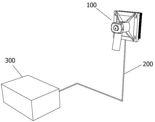
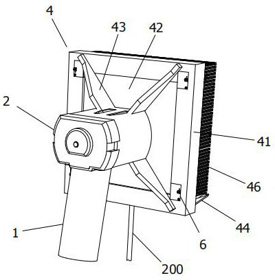
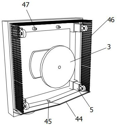
[0047] like figure 1 As shown, a spray-type wall grinding system with adjustable grinding depth provided in this embodiment includes a portable wall grinding machine 100 , a water collecting pipe 200 and a water collecting tank 300 . combine figure 2 and image 3As shown, the portable wall grinder 100 includes a handle 1 , a drive motor 2 , a grinding cutter head 3 , a dust cover 4 , several hydraulic buffer components 5 , a grinding depth adjustment component 6 and a water mist nozzle 47 . Can adopt prior art for holding handle 1, driving motor 2 and grinding cutter head 3, and its specific structure, connection relation and working principle are not described in detail.

[0048] The back of the dust cover 4 is fixed on the casing of the drive motor 2 , and the grinding cutter head 3 is located on the front of the dust cover 4 and is fixedly connected with the transmission shaft of the drive motor 2 . Further, the dustproof cover 4 includes a hard outer frame 41, a transp...

Embodiment 2

[0059] This embodiment provides a construction method for wall grinding, using the spray-type wall grinding system with adjustable grinding depth in Embodiment 1, according to the following Figure 11 to Figure 13 , and combined with Figure 1 to Figure 10 Describe the construction method further. Described construction method comprises the steps:

[0060] Step 1. Determine the depth to be polished on the wall, adjust the position of the stepped limit card 61 through the adjustment button 62, and set all the grinding depth adjustment components 6 of the portable wall grinder to the required grinding depth;

[0061] Step two, such as Figure 11 As shown, start the portable wall grinder, turn on the water mist nozzle 47, and gradually press the grinding cutter head to the wall 8 to grind out a circular groove, as Figure 12 As shown, when the grinding depth reaches the maximum, move the portable wall grinder downwards along the wall 8, and grind to form a vertical strip groov...


PUM


Abstract

The invention discloses a construction method for wall surface grinding. A spray type wall surface grinding system with adjustable grinding depth is adopted. The grinding system includes a portable wall surface grinding machine, a water collecting pipe and a water collecting tank. The portable wall surface grinding The grinding machine includes several hydraulic buffer components, grinding depth adjustment components and water mist nozzles. The method includes: step 1, setting all grinding depth adjustment components to the required grinding depth; step 2, starting the portable wall grinder, turning on the water mist nozzle, and moving the portable wall surface downwards when the grinding depth reaches the maximum. Wall grinder, grind to form a vertical strip groove; step 3, move the portable wall grinder to the adjacent area to be polished to form a second strip groove; step 4, repeat step 3, Until the surface sanding of the wall is completed. The method can realize spray dust removal and precise control of grinding depth, and has the advantages of high construction efficiency and good construction quality.

Description

technical field [0001] The invention relates to a construction method for grinding walls, and belongs to the technical field of building wall transformation. Background technique [0002] When the facade of a building brick wall is repaired with brick powder, it is necessary to polish the old surface of the existing brick wall to expose a solid base layer. The surface layer is polished to remove protrusions and burrs, etc. [0003] When grinding the wall, it is necessary to control the grinding depth, not only to polish the surface of the wall in place, but also to maintain the consistency of the overall grinding depth of the wall. At present, the operator controls the grinding depth by controlling the force applied to the grinding machine, and the grinding accuracy is difficult to guarantee, resulting in poor construction quality and low construction efficiency. Contents of the invention [0004] Aiming at the problems that the grinding precision is difficult to guarant...

Claims


Application Information

Patent Timeline
Patent Type & Authority Patents(China)
IPC IPC(8): B24B7/18B24B23/02B24B41/02B24B47/20B24B47/26B24B49/00B24B51/00B24B55/00B24B55/05B24B55/10B01D47/06
CPCB01D47/06B24B7/182B24B23/02B24B41/02B24B47/20B24B47/26B24B49/00B24B51/00B24B55/00B24B55/052B24B55/102
Inventor 任瑛楠黄轶谷志旺张波陈雪峡孙沈鹏蔡观生王伟茂何娇张少伟
Owner SHANGHAI NO 4 CONSTR
Learn More