
Buffer belt wheel and buffer gear train mechanism with same

A buffer belt and buffer wheel technology, which is applied to components with teeth, belts/chains/gears, mechanical equipment, etc., can solve the problem of reduced shock absorption capacity of the power system, reduced durability and reliability, and excessive alignment requirements of the wheel train. Advanced problems, to achieve the effect of convenient impact force transmission, compensation for alignment errors, and remarkable cushioning effect

Pending Publication Date: 2020-10-02
ANHUI JIANGHUAI NAVISTAR DIESEL ENGINE CO LTD
View PDF0 Cites 0 Cited by
  • Summary
  • Abstract
  • Description
  • Claims
  • Application Information

AI Technical Summary

Problems solved by technology

[0003] 1. Using an ordinary pulley device, the transmission belt will receive a large impact force when the driving wheel is applied transiently, the transmission belt will slip and produce abnormal noise, or even age and break, posing a great safety hazard
[0004] 2. The use of ordinary pulley devices cannot eliminate vibration, and vibration will affect the reliability of gear train components. Long-term vibration will lead to failure of components, and at the same time, it will reduce the shock absorption capacity of the power system and increase the vibration amplitude. , durability reliability will be reduced
[0005] 3. The use of ordinary pulley devices requires too high alignment between the wheel trains, which is more prone to abnormal noise and abnormal wear of the belt, greatly reducing the service life of the belt and accessory bearings
[0006] 4. Using ordinary pulley devices, because the transient load effect brought by the impact force on the accessories cannot be quickly eliminated, the service life of the accessories will be significantly reduced, and the cost of use will increase a lot

Method used


Image

  • Buffer belt wheel and buffer gear train mechanism with same
  • Buffer belt wheel and buffer gear train mechanism with same
  • Buffer belt wheel and buffer gear train mechanism with same

Examples


Embodiment Construction

[0031] The embodiments of the present invention are described in detail below. This embodiment is implemented on the premise of the technical solution of the present invention, and detailed implementation methods and specific operating procedures are provided, but the protection scope of the present invention is not limited to the following implementation example.

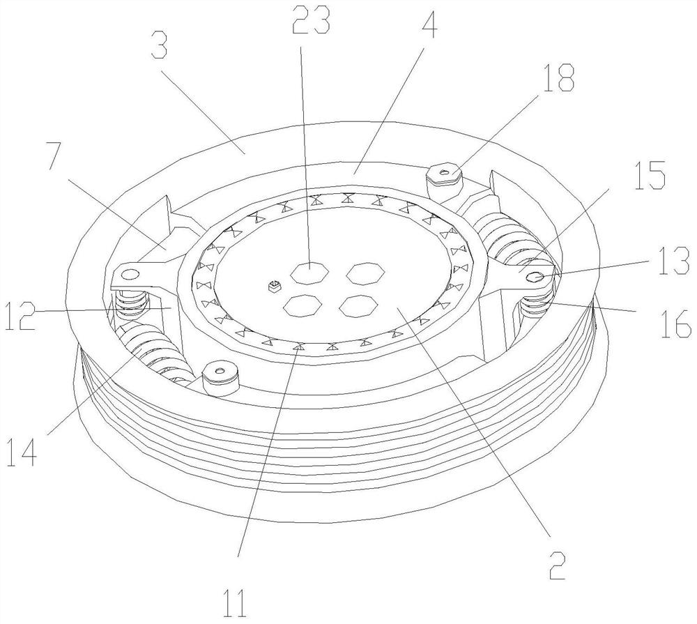
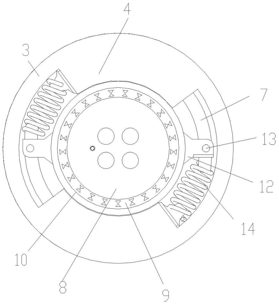
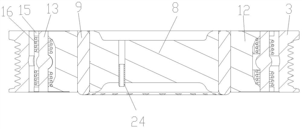
[0032] see Figure 1 to Figure 6 , this embodiment discloses a buffer pulley, comprising a buffer wheel seat 2 coaxially arranged inside and outside and a buffer wheel outer ring 3, an annular gap is formed between the outer ring of the buffer wheel seat 2 and the inner ring of the buffer wheel outer ring 3, and the ring Two cylinders 4 are arranged in the gap, and the two cylinders 4 are center-symmetrically distributed relative to the center point of the buffer pulley 1. The cylinder bodies of the two cylinders 4 are respectively fixed with the buffer wheel outer ring 3, and the cylinder bodies of each cylinder 4...


PUM


Abstract

The invention discloses a buffer belt wheel and a buffer gear train mechanism with the same. The buffer belt wheel comprises a buffer wheel seat and a buffer wheel outer ring, wherein the buffer wheelseat is arranged coaxial with the buffer wheel outer ring inside and outside, two air cylinders are arranged in an annular gap between an outer circle of the buffer wheel seat and an inner circle ofthe buffer wheel outer ring, the buffer wheel outer ring is fixed to cylinder bodies of the two air cylinders, a piston is slidably disposed in an arc-shaped cavity of the cylinder body of each air cylinder, an arc-shaped piston rod is arranged at one end of each piston, the ends of the arc-shaped piston rods extend outwards from the ends of the cylinder bodies and are located in the annular gap,the center line of the arc-shaped piston rods and the center line of the arc-shaped cavities are concentric with the buffer belt wheel, two lugs are arranged on two sides of the buffer wheel seat, hinging of the arc-shaped piston rods and the lugs is realized through pin shafts on the lugs, and a circumferential buffer spring is arranged in the gap between the outer end of the arc-shaped piston rod of each air cylinder and the cylinder body of the other air cylinder. The buffer belt wheel has the advantages that the transient impact force can be quickly released, and the buffering effect is significant.

Description

technical field [0001] The invention relates to the technical field of transmission mechanisms, in particular to a buffer pulley and a buffer train mechanism with the buffer pulley. Background technique [0002] The existing transmission system usually uses a common pulley device, and the pulley is also a common pulley without a buffer mechanism. This structure has the following defects: [0003] 1. Using an ordinary pulley device, the transmission belt will receive a large impact force when the driving pulley is applied transiently, the transmission belt will slip and produce abnormal noise, or even age and break, which poses a great safety hazard. [0004] 2. The use of ordinary pulley devices cannot eliminate vibration, and vibration will affect the reliability of gear train components. Long-term vibration will lead to failure of components, and at the same time, it will reduce the shock absorption capacity of the power system and increase the vibration amplitude. , dura...

Claims


Application Information

Patent Timeline
Patent Type & Authority Applications(China)
IPC IPC(8): F16H7/02F16H7/08F16H55/36F16H57/028
CPCF16H7/02F16H7/0836F16H55/36F16H2055/366
Inventor 葛锐朱文军胡志胜张军瑞李健辛雪军肖秋红范孝康
Owner ANHUI JIANGHUAI NAVISTAR DIESEL ENGINE CO LTD
Learn More