
Motor winding active discharge control method based on direct-current voltage feedback control

A feedback control, motor winding technology, applied in the direction of motors, electric vehicles, electrical devices, etc., can solve the problems of severe capacitor voltage fluctuations, unfavorable device heat dissipation, large risk coefficient, etc., and achieve the effect of improving safety.

Active Publication Date: 2020-10-02
DELPHI TECH SUZHOU CO LTD
View PDF8 Cites 0 Cited by
  • Summary
  • Abstract
  • Description
  • Claims
  • Application Information

AI Technical Summary

Problems solved by technology

The problem with the step input is that due to the small error of the zero angle, a small torque is caused, and the current is a constant DC during the process of stopping and powering off, which is not good for the heat dissipation of the device
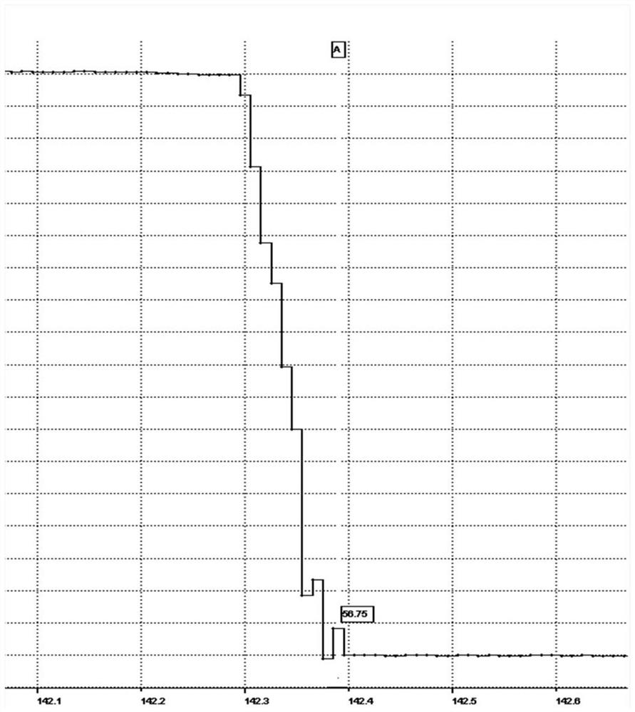
Problems with square wave input, such as figure 1 As shown, due to the rapid change of the current command, the voltage on the capacitor fluctuates violently, and there are jumps and rises, even jumping from a safe voltage below 60v to more than 60v. This voltage response is not ideal and dangerous.
[0004] The prior art discloses a method for rapid discharge of a high-voltage capacitor of an electric vehicle motor controller. When the terminal voltage of the capacitor is greater than the safe voltage, the stator winding of the permanent magnet synchronous motor is used for rapid discharge. When the voltage jump exceeds the safe voltage threshold, the risk factor is large

Method used

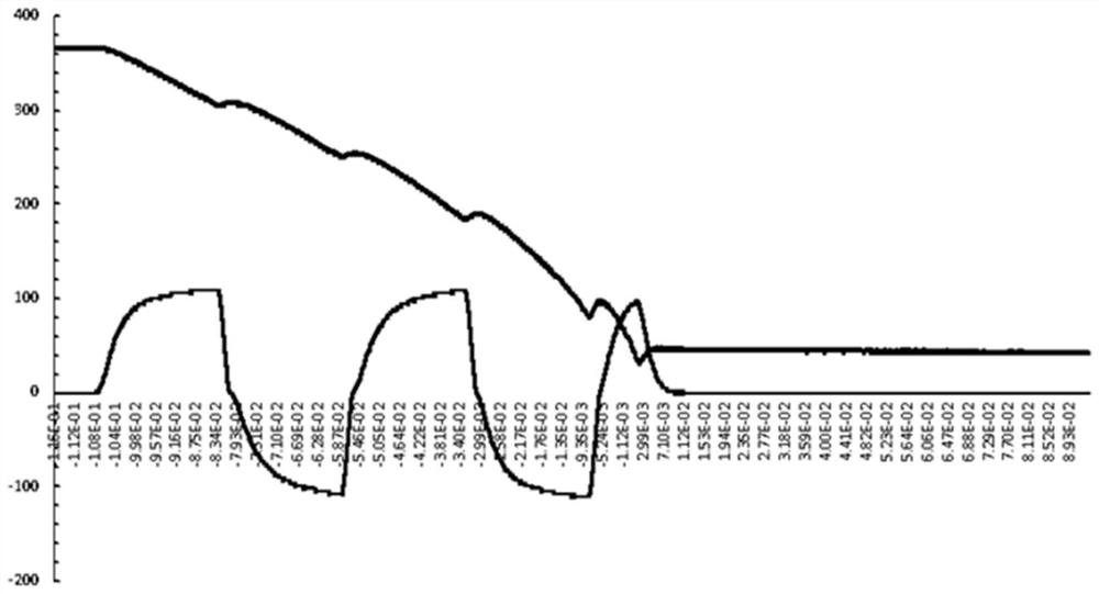

Image

  • Motor winding active discharge control method based on direct-current voltage feedback control
  • Motor winding active discharge control method based on direct-current voltage feedback control
  • Motor winding active discharge control method based on direct-current voltage feedback control

Examples


Embodiment Construction

[0033] The present invention will be described in detail below in conjunction with the accompanying drawings and specific embodiments. This embodiment is carried out on the premise of the technical solution of the present invention, and detailed implementation and specific operation process are given, but the protection scope of the present invention is not limited to the following embodiments.

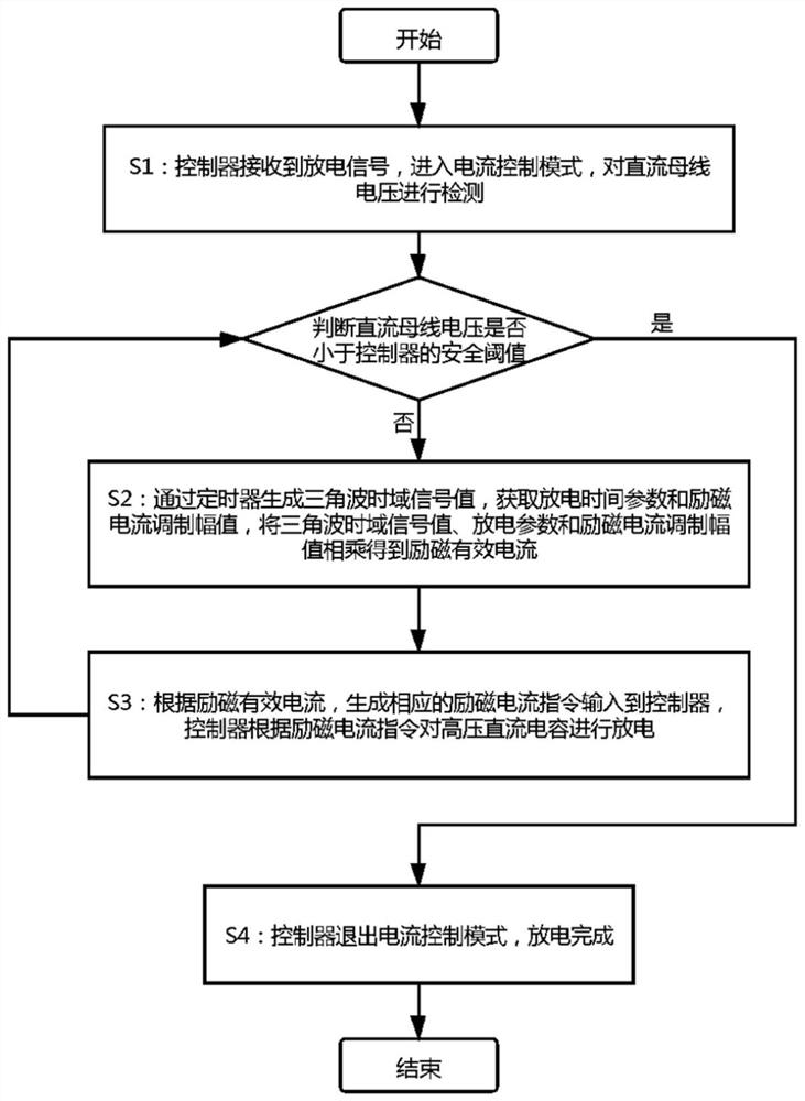
[0034] Such as figure 2 As shown, a motor winding active discharge control method based on DC voltage feedback control, the discharge is controllable, and there is no danger of voltage jump during the inverter process, which specifically includes the following steps:

[0035] Step S1: The controller receives the discharge signal, enters the current control mode, and detects the DC bus voltage. If the DC bus voltage is lower than the safety threshold of the controller, go to step S4, otherwise go to step S2;

[0036] Step S2: Generate the triangular wave time-domain signal value by t...


PUM


Abstract

The invention relates to a motor winding active discharge control method based on direct-current voltage feedback control. The method specifically comprises the following steps that S1, receiving a discharge signal by a controller, entering into a current control mode and detecting the voltage of a direct-current bus, if the voltage of the direct-current bus is smaller than a safety threshold value of the controller, executing step S4 , and otherwise, executing step S2; S2, generating a triangular wave time domain signal value through a timer, obtaining a discharge time parameter and an exciting current modulation amplitude, and multiplying the triangular wave time domain signal value, the discharge parameter and an exciting current modulation amplitude to obtain an exciting effective current; S3, generating a corresponding exciting current instruction according to the effective exciting current, inputting the exciting current instruction into the controller, discharging a high-voltagedirect-current capacitor by the controller according to the exciting current instruction, and turning to the step S1; and S4, quitting the current control mode of the controller. Compared with the prior art, the method has the advantages of reducing the danger of voltage jump, improving the driving safety of electric vehicles and the like.

Description

technical field [0001] The invention relates to the technical field of rapid discharge of high-voltage capacitors for electric vehicles, in particular to an active discharge control method for motor windings based on DC voltage feedback control. Background technique [0002] According to the safety requirements of electric vehicles in terms of functional safety, fault protection, and electric shock protection, after an electric vehicle crashes, the on-board motor controller should reduce the voltage of the high-voltage DC capacitor to below the safe voltage range of 60v within 3s. Because the passive discharge method cannot achieve such a fast discharge speed, the current on-board motor controllers have an active discharge function. After the electric vehicle is disconnected from the power supply or a collision occurs, the system will quickly reduce the DC bus voltage to below 60v. There are two ways to realize the active discharge function. The first type is to discharge th...

Claims


Application Information

Patent Timeline
Patent Type & Authority Applications(China)
IPC IPC(8): B60L3/00
CPCB60L3/00B60L3/0046Y02T10/64
Inventor 徐哲顾捷辛建成熊壮壮陈帅
Owner DELPHI TECH SUZHOU CO LTD
Learn More