Buck-boost inverter and control method thereof

A technology of inverter and buck-boost, which is applied in the field of buck-boost inverter and its control, which can solve the problems of reducing system safety and efficiency, so as to improve safety and efficiency, reduce components and reduce circuit cost Effect

Active Publication Date: 2020-09-22
ANHUI UNIVERSITY OF TECHNOLOGY
View PDF8 Cites 1 Cited by
  • Summary
  • Abstract
  • Description
  • Claims
  • Application Information

AI Technical Summary

Problems solved by technology

However, the inverter proposed in the above patent still has leakage current in the circuit, which reduces the safety and efficiency of the system.

Method used


Image

  • Buck-boost inverter and control method thereof
  • Buck-boost inverter and control method thereof
  • Buck-boost inverter and control method thereof

Examples


Embodiment 1

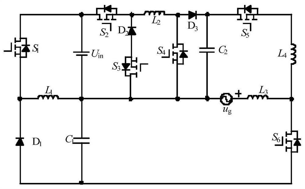
[0048] Such as figure 1 As shown, this embodiment proposes a buck-boost inverter, including a first filter inductor L 1 , the second filter inductance L 2 , the third filter inductance L 3 , the fourth filter inductor L 4 , the first switch tube S 1 , the second switch tube S 2 , the third switch tube S 3 , the fourth switch tube S 4 , the fifth switch tube S 5 , the sixth switch tube S 6 , the first filter capacitor C 1 , the second filter capacitor C 2 , the first diode D 1 , the second diode D 2 , the third diode D 3 ;in,

[0049] The second switch tube S 2 The first end and the input power U in One end and the first switch tube S 1 The first end is connected, the second switching tube S 2 The second terminal and the second diode D 2 Cathode and second filter inductor L 2 One end connection;

[0050] second diode D 2 Anode and the third switch tube S 3 the second end connection;

[0051] The third switch tube S 3 The first end and the input power U ...

Embodiment 2

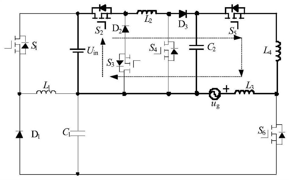
[0062] On the basis of the buck-boost inverter described in Embodiment 1, this embodiment provides a control method for the buck-boost inverter:

[0063] When input power U in >Output side voltage u g , output side voltage u g In the positive half cycle, the first switching tube S 1 , the fourth switch tube S 4 , the sixth switch tube S 6 Normally off, the third switch tube S 3 , the fifth switch tube S 5 Normally open, the second switch tube S 2 switching high frequency, such as figure 2 and image 3 shown. It can be adjusted by adjusting the second switch tube S 2 The duty cycle to adjust the grid current i g The size of the guarantee grid current i g and grid voltage u g Same frequency and same phase.

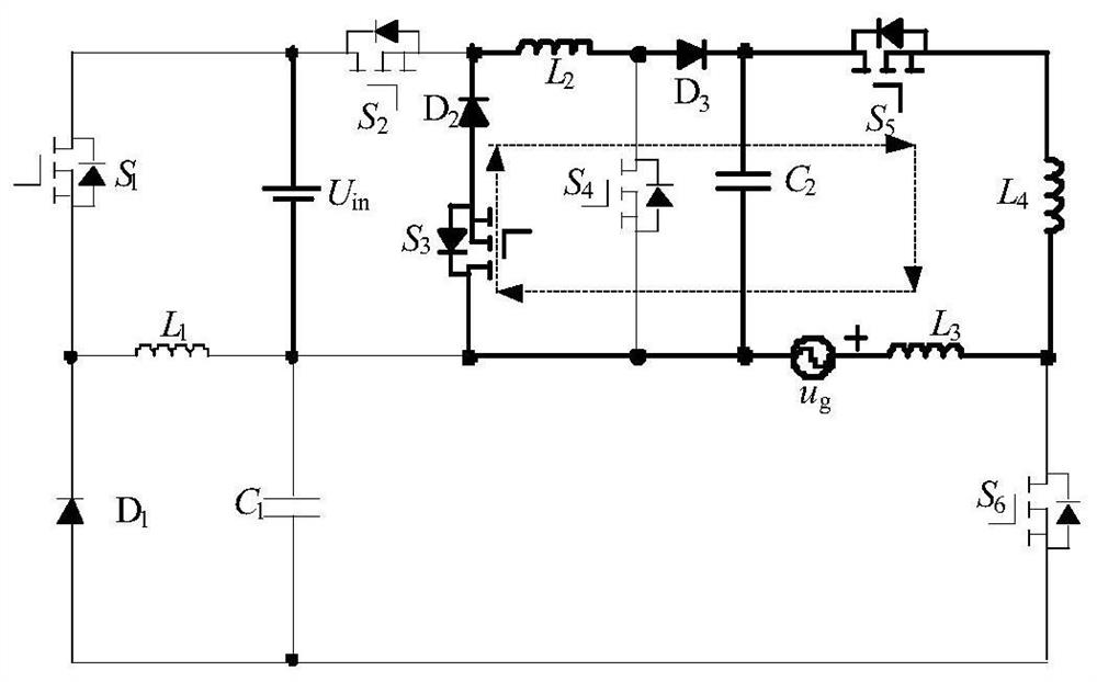
[0064] When input power U in >Output side voltage u g , output side voltage u g In the negative half cycle, the second switching tube S 2 , the third switch tube S 3 , the fourth switch tube S 4 , the fifth switch tube S 5 Normally off, the sixth switch...


PUM


Abstract

The invention provides a buck-boost inverter and a control method thereof, and belongs to the technical field of power conversion. The circuit comprises an input power supply Uin, first to sixth switching tubes S1 to S6, first and second filter capacitors C1 and C2, first to fourth filter inductors L1 to L4, and first to third diodes D1 to D3. The first end of the S2 is connected with the Uin andthe first end of the S1, and the second end of the S2 is connected with the cathode of the D2 and the L2; the anode of D2 is connected with the second end of S3; the first end of the S3 is connected with the other end of the Uin, the C1, the L1, the second end of the S4, the C2 and the output side; the other end of the L2 is connected with the first end of the S4 and the anode of the D3; the cathode of D3 is connected with the other end of C2 and the first end of S5; the second end of the S5 is connected with the L4; the other end of the L4 is connected with the L3 and the first end of the S6,and the other end of the L3 is connected with the other end of the output side; the other end of the S6 and the second end of the C1 are connected with the anode of the D1; and the cathode of the D1is connected with the other end of the L1 and the second end of the S1. The input side and the output side supply ground to eliminate leakage current, and the direct connection problem of a traditional bridge type inverter is solved.

Description

technical field [0001] The present invention relates to the technical field of power conversion, and more specifically, to a buck-boost inverter and a control method thereof. Background technique [0002] With the increasing environmental pollution and the continuous shortage of fossil energy, new energy power generation technologies such as solar energy, wind energy, and fuel cell power generation have attracted people's attention due to their advantages such as pollution-free and renewable. However, photovoltaic power generation, wind energy and fuel cell power generation output electric energy as direct current, while grid voltage is alternating current. Therefore, the grid-connected inverter is a key interface circuit between new energy generation technology and the grid. Since photovoltaic power generation and fuel cells are easily disturbed by the external environment, the output voltage varies in a wide range, which leads to the output voltage being sometimes higher ...

Claims


Application Information

Patent Timeline
Patent Type & Authority Applications(China)
IPC IPC(8): H02M7/48
CPCH02M7/48Y02B70/10
Inventor 胡雪峰龙子康江顺德沈浩张玉勃姚志垒杨云虎郑诗程
Owner ANHUI UNIVERSITY OF TECHNOLOGY
Why Eureka
Try Eureka