A valve with a guide assembly

A technology of guiding components and valves, which is applied in the direction of valve devices, valve details, valve housing structures, etc., can solve the problems of reducing water flow rate, valves are easy to enter sand and gravel, and no power mechanism is installed, so as to achieve the effect of increasing smoothness

Active Publication Date: 2021-11-19
YANCHENG OURUN PETROCHEMICAL EQUIP MFG CO LTD
View PDF0 Cites 0 Cited by
  • Summary
  • Abstract
  • Description
  • Claims
  • Application Information

AI Technical Summary

Problems solved by technology

[0003] However, in order to prevent non-staff from turning the traditional municipal water stop valve installed on the road, the turntable will be disassembled after the valve is installed, and the top of the rotating screw rod will be exposed outside the valve after the turntable of the valve is removed. Then the valve installed on the road plate is easy to enter the sand and gravel. After the sand and gravel enter the surface of the valve, it is easy to jam the screw of the valve, resulting in the top of the screw being unable to engage and rotate with the turntable. The sand and gravel need to be cleaned, resulting in The valve cannot be opened quickly; and the valves currently installed on urban roads can only control water. There is no power mechanism inside the valve body, and the impurities in the water are not filtered. Clogged valve, reduced water flow rate

Method used


Image

  • A valve with a guide assembly
  • A valve with a guide assembly
  • A valve with a guide assembly

Examples


Embodiment Construction

[0024] In order to make the technical means, creative features, goals and effects achieved by the present invention easy to understand, the present invention will be further described below in conjunction with specific embodiments.

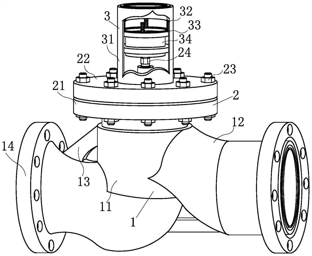
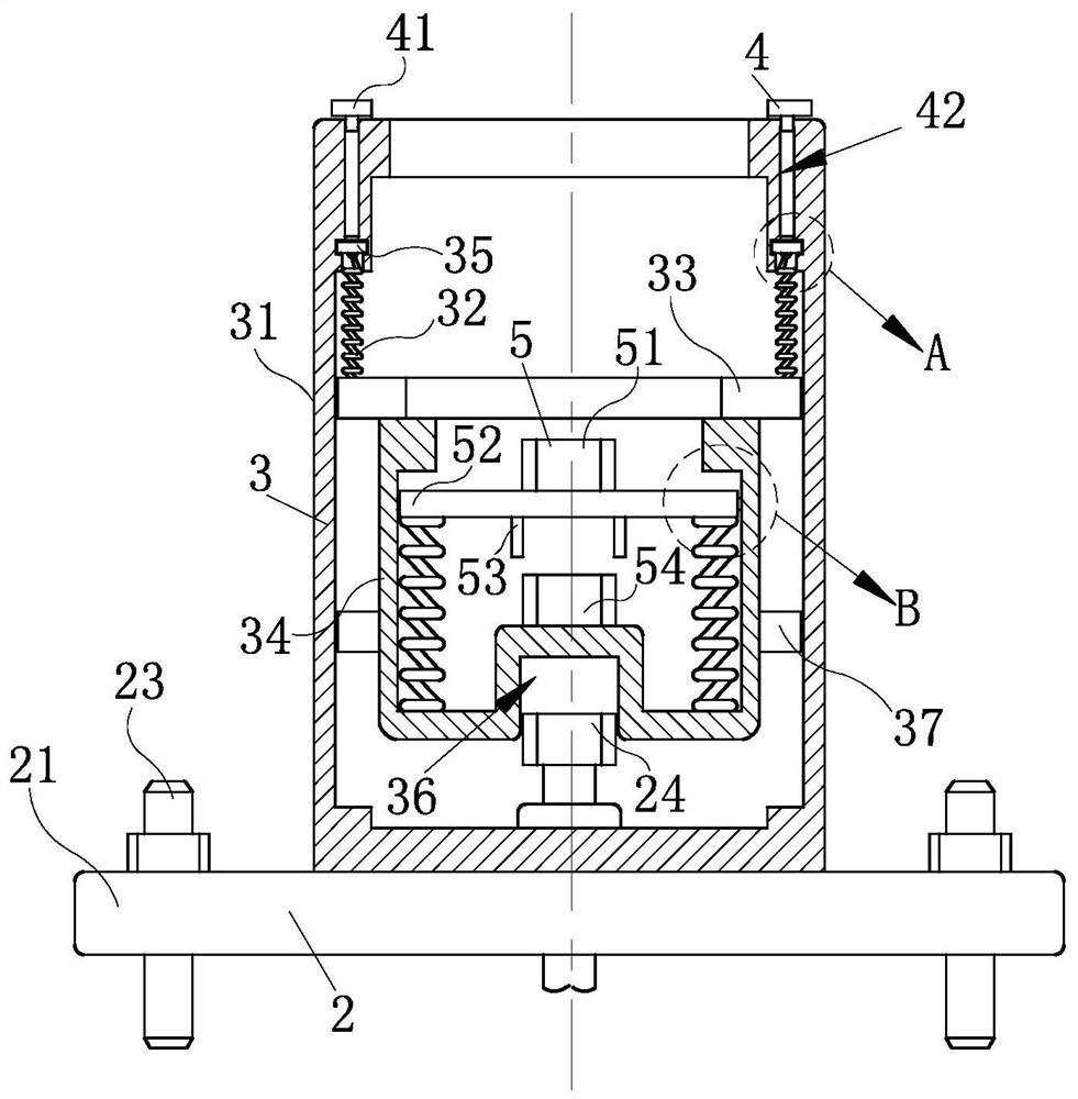
[0025] Such as Figure 1-Figure 6 As shown, a valve with a guide assembly described in the present invention includes a control mechanism 1, a fixing mechanism 2, a guide mechanism 3, a lubrication mechanism 4, a protection mechanism 5 and a filter mechanism 6; The top of the control mechanism 1 is equipped with the fixing mechanism 2, and the top of the fixing mechanism 2 is installed with the guide mechanism 3 for protecting the control mechanism 1 and facilitating the insertion of the removal tool. The inside of the mechanism 3 is slidingly connected with the protection mechanism 5 used to rotate the control mechanism 1 and prevent the sandstone from blocking the control mechanism 1. The fixing mechanism 2 and the guide mechanism 3 are in a "T"...


PUM


Abstract

The invention relates to the field of valves, specifically a valve with a guide assembly, including a control mechanism, a fixing mechanism, a guiding mechanism, a lubricating mechanism, a protection mechanism and a filtering mechanism; A guiding mechanism that guides the rotating tool, and the internal sliding connection of the guiding mechanism has a protective mechanism for adjusting the control mechanism to facilitate the adjustment of the control mechanism, and also avoids sand and gravel stuck to the control mechanism, which makes it difficult to adjust the control mechanism; A filter mechanism is installed inside the control mechanism. When the control mechanism is installed, the water inlet pipe is in conflict with the filter mechanism, so that the water can be filtered when the water flows, which is beneficial for residents to use water, and also avoids the blockage of the control mechanism and protects the control mechanism; A lubricating mechanism is installed on the top of the mechanism. When the control mechanism is adjusted, the lubricating mechanism is opened and lubricating oil is added to the inside, which is beneficial to the rotation of the guiding mechanism when the control mechanism is adjusted.

Description

technical field [0001] The invention relates to the field of valves, in particular to a valve with a guide assembly. Background technique [0002] Valves are pipeline accessories used to open and close pipelines, control flow direction, adjust and control the parameters (temperature, pressure and flow) of the conveying medium. According to its function, it can be divided into shut-off valve, check valve, regulating valve, etc. The valve is the control component in the fluid delivery system, with the functions of cut-off, regulation, flow diversion, reverse flow prevention, pressure stabilization, diversion or overflow pressure relief, etc. Function. Valves used in fluid control systems range from the simplest cut-off valves to various valves used in extremely complex automatic control systems, with a wide variety of varieties and specifications. [0003] However, in order to prevent non-staff from turning the traditional municipal water stop valve installed on the road, th...

Claims


Application Information

Patent Timeline
Patent Type & Authority Patents(China)
IPC IPC(8): F16K27/00F16K27/08F16K27/12F16K31/50F16N7/00F16N19/00F16N21/06B01D35/04B01D29/31B01D29/96
CPCB01D29/31B01D29/96B01D35/04F16K27/00F16K27/08F16K27/12F16K31/50F16N7/00F16N19/00F16N21/06
Inventor 不公告发明人
Owner YANCHENG OURUN PETROCHEMICAL EQUIP MFG CO LTD
Why Eureka
Try Eureka