
Three-wire drawing steel pipe machine and using method thereof

A steel pipe drawing machine and three-wire technology, applied in the direction of wire drawing dies, etc., to achieve the effect of reducing resistance and facilitating replacement

Inactive Publication Date: 2020-09-15
常州亿仁机械科技有限公司
View PDF7 Cites 2 Cited by
  • Summary
  • Abstract
  • Description
  • Claims
  • Application Information

AI Technical Summary

Problems solved by technology

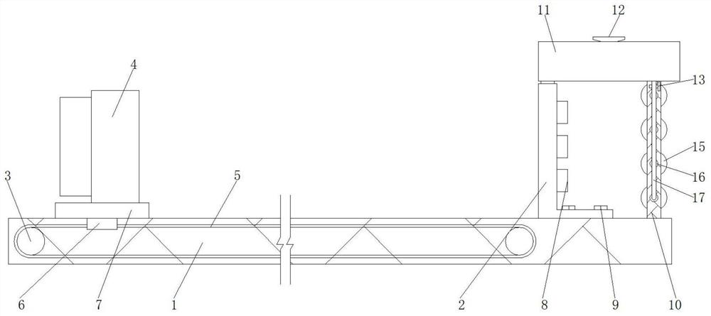
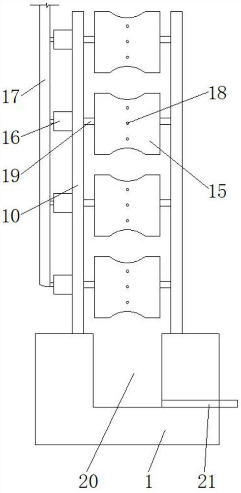
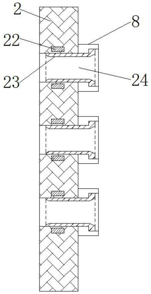
[0004] The purpose of the present invention is to provide a three-wire drawing steel pipe machine and its use method. By setting a replaceable drawing cylinder and inserting it into the slot, when drawing steel pipes with different diameters, the drawing cylinder can be replaced conveniently. In this way, it is convenient to draw different steel pipes. In addition, there are structures such as a brush cylinder and an oil tank on the right side of the drawing plate, which can conveniently apply oil to the drawn steel pipes, thereby improving work efficiency and reducing oil waste. questions raised in technology

Method used


Image

  • Three-wire drawing steel pipe machine and using method thereof
  • Three-wire drawing steel pipe machine and using method thereof
  • Three-wire drawing steel pipe machine and using method thereof

Examples


Embodiment Construction

[0029] In order to make the technical means, creative features, goals and effects achieved by the present invention easy to understand, the present invention will be further described below in conjunction with specific embodiments.

[0030] In describing the present invention, it should be understood that the terms "upper", "lower", "front", "rear", "left", "right", "top", "bottom", "inner", " The orientation or positional relationship indicated by "outside", etc. is based on the orientation or positional relationship shown in the drawings, and is only for the convenience of describing the present invention and simplifying the description, rather than indicating or implying that the referred device or element must have a specific orientation, so as to Specific orientation configurations and operations, therefore, are not to be construed as limitations on the invention.

[0031] In the description of the present invention, it should be noted that, unless otherwise specified and...


PUM


Abstract

The invention relates to the technical field of three-wire drawing machines, and discloses a three-wire drawing steel pipe machine and a using method thereof. The three-wire drawing steel pipe machinecomprises a frame and a drawing plate, the drawing plate is installed on the upper surface of the right side of the frame through bolts, and a drawing mechanism and an oiling mechanism are arranged above the frame; the drawing mechanism comprises a chain wheel, a clamping mechanism, a chain, a sliding block, a moving plate, a sleeve, a rotating shaft, a magnet, a stretching cylinder and an inserting groove; the number of the chain wheels is two, the chain wheels are rotatably installed on the two sides of the interior of the frame through rotating shafts, a chain is in transmission connectionbetween the chain wheels on the two sides, and a movable plate is slidably arranged on the surface of the frame above the chain. According to the steel pipe drawing device, the replaceable stretchingcylinder is inserted into the inserting groove, when steel pipes with different diameters are drawn, the stretching cylinder can be conveniently replaced, so that the different steel pipes are conveniently drawn, and in addition, structures such as a brush cylinder and an oil tank are arranged on the right side of the drawing plate, so that the drawn steel pipes can be conveniently oiled; therefore, the working efficiency is improved, and the waste of oil is reduced.

Description

technical field [0001] The invention relates to the technical field of three-wire drawing machines, in particular to a three-wire drawing steel pipe machine and a method for using the same. Background technique [0002] At present, the drawing machine is an industrial equipment composed of mechanical equipment, lubrication equipment, electrical equipment, hydraulic and pneumatic systems, etc., and is an equipment for drawing metal materials. The drawing machine is a device used for drawing and processing metals at room temperature. Its ability is often expressed by the maximum pull-out force. According to different structures, the drawing machine can be divided into chain drawing machine, hydraulic drawing machine, and reel drawing machine. The three-wire drawing steel pipe machine is a machine for drawing steel pipes. [0003] There are some problems in the use of the steel pipe drawing machine. For example, when drawing steel pipes of different diameters, it is troubleso...

Claims


Application Information

Patent Timeline
Patent Type & Authority Applications(China)
IPC IPC(8): B21C9/00B21C1/22B21C1/30B21C1/28B21C3/02
CPCB21C1/22B21C1/28B21C1/30B21C3/02B21C9/00
Inventor 王秀
Owner 常州亿仁机械科技有限公司
Learn More