
Cutter damage real-time monitoring method based on spindle vibration feature fusion

A technology of real-time monitoring and feature fusion, applied in the direction of manufacturing tools, measuring/indicating equipment, instruments, etc., can solve a lot of time and cost, lack of physical modeling, indirect monitoring methods can not determine the cutting load and other problems

Active Publication Date: 2020-09-11
XI AN JIAOTONG UNIV
View PDF6 Cites 12 Cited by
  • Summary
  • Abstract
  • Description
  • Claims
  • Application Information

AI Technical Summary

Problems solved by technology

However, the data model uses the data to fit the change law of the actual system, and lacks the process of obtaining the law through physical modeling. Therefore, there is a problem that a large amount of experimental data is required for training in the early stage.
Moreover, in actual processing, the process parameters are changeable and there are many kinds of materials, so it takes a lot of time and cost to accumulate data.
[0004] To sum up, the current direct monitoring method for tool damage needs to be shut down, which affects the processing efficiency; the indirect monitoring method cannot determine whether the change of cutting load is caused by tool damage, and lacks mechanism analysis, so a large amount of data is required to fit the law

Method used


Image

  • Cutter damage real-time monitoring method based on spindle vibration feature fusion
  • Cutter damage real-time monitoring method based on spindle vibration feature fusion
  • Cutter damage real-time monitoring method based on spindle vibration feature fusion

Examples


Embodiment Construction

[0115] The present invention will be described in detail below with reference to the drawings and embodiments.

[0116] A real-time monitoring method for tool damage based on spindle vibration feature fusion, including the following steps:

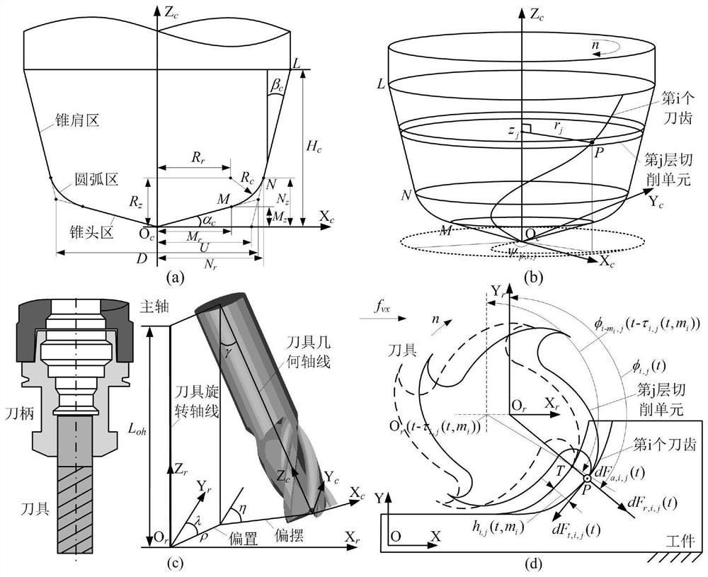
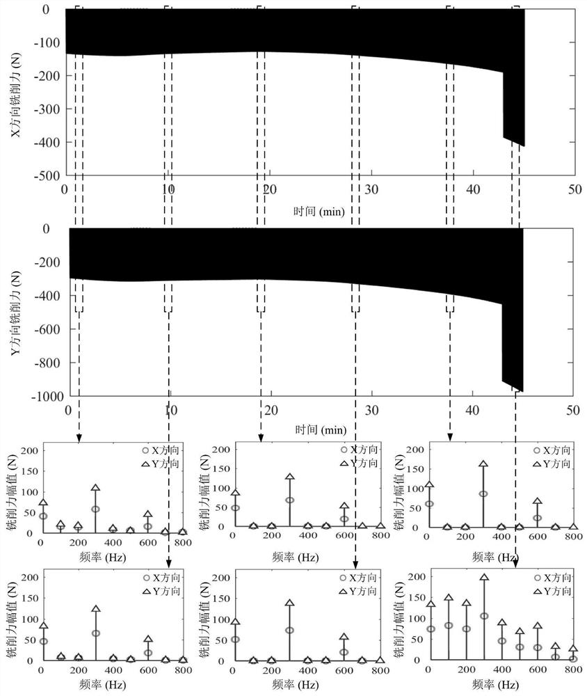
[0117] Step 1) For the milling process, analyze the tool damage process, establish a calculation model of the cutting layer thickness considering the tool eccentricity and damage, calculate the milling force, and analyze the time domain and frequency domain characteristics of the milling force;

[0118] 1.1) The damage process of the tool in the milling process:

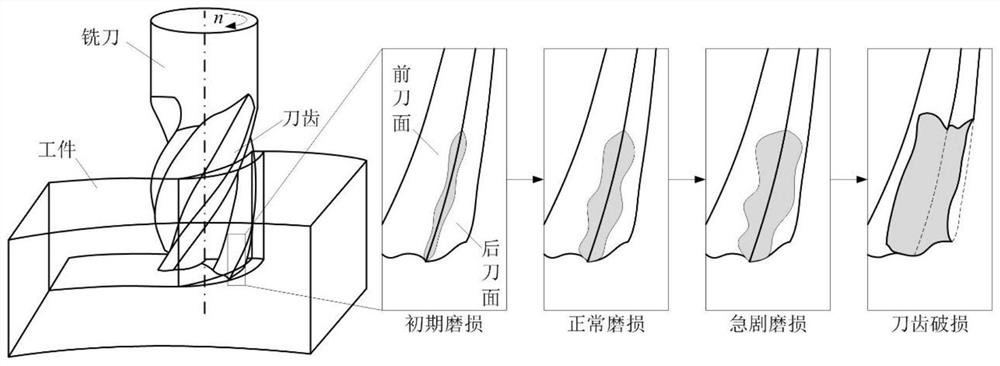
[0119] Such as figure 1 As shown, during the machining process, the cutting force and cutting heat will be generated when the tool and the workpiece are in contact, which will cause the front and rear face of the tool teeth to wear under the effect of thermal coupling. After the tool wears, it will cause the increase of the cutting force, especially It is the alternating force, friction...


PUM


Abstract

The invention relates to a cutter damage real-time monitoring method based on spindle vibration feature fusion. The method comprises the steps that firstly, for a milling process, a cutter damage process is analyzed, a cutting layer thickness calculation model considering cutter eccentricity and damage is established, milling force calculation is carried out, and milling force time domain and frequency domain characteristics are analyzed; experimental testing and modal parameter identification are conducted on a tool nose point-spindle head transfer function, spindle vibration response under an excitation effect of milling force is calculated, and time domain and frequency domain characteristics of the vibration response are analyzed; frequency domain amplitudes of spindle vibration displacement responses in the X direction and the Y direction are fused, and a cutter damage characteristic is defined; and real-time data acquisition, dynamic extraction and splicing are carried out on a spindle vibration acceleration signal, a cutter damage characteristic value is calculated, and the cutter damage characteristic value is compared with a threshold value to judge whether a cutter is damaged or not in real time. According to the method, rapid and accurate cutter damage monitoring can be realized, and an implementation scheme is simple and effective.

Description

Technical field [0001] The invention belongs to the technical field of intelligent cutting processing, and particularly relates to a method for real-time monitoring of tool damage based on spindle vibration feature fusion. Background technique [0002] Tool damage will directly affect the surface quality and dimensional accuracy of the workpiece, and in severe cases, it will damage the machine. In the actual cutting process, whether the tool is damaged or not depends on the experience of the worker to judge, such as listening to the sound of the cutting process, feeling the vibration of the machine tool, and visual observation when it is stopped. However, due to the lack of manual intervention in a production line with one person, multiple machines and unattended, there will be cases of untimely and frequent tool replacement. Failure to replace the tools in time will result in substandard parts quality, and even produce waste; frequent tool replacement will cause long downtime a...

Claims


Application Information

Patent Timeline
IPC IPC(8): B23Q17/09G06K9/62
CPCB23Q17/0971G06F18/253
Inventor 张星潘天航赵万华闫文彪张俊尹佳
Owner XI AN JIAOTONG UNIV
Learn More