Photo-thermal micro-thruster based on annular core capillary optical fiber

A micro-propeller and capillary technology, which is applied in the components, instruments, optics and other directions of pumping devices for elastic fluids, can solve the problems of unused and optical-thermal effect characteristics of optical fibers.

Inactive Publication Date: 2020-09-08
GUILIN UNIV OF ELECTRONIC TECH
View PDF9 Cites 3 Cited by
  • Summary
  • Abstract
  • Description
  • Claims
  • Application Information

AI Technical Summary

Problems solved by technology

[0006] In the above types of microfluidic systems related to optical fibers, the sample liquid often needs to be driven, controlled or performed various operations, and the photothermal effect characteristics in the optical fiber are not used.

Method used


Image

  • Photo-thermal micro-thruster based on annular core capillary optical fiber
  • Photo-thermal micro-thruster based on annular core capillary optical fiber
  • Photo-thermal micro-thruster based on annular core capillary optical fiber

Examples


Embodiment Construction

[0051] The present invention will be further described below in conjunction with the accompanying drawings and specific embodiments.

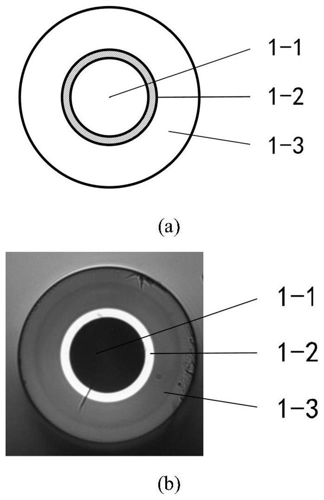
[0052] figure 1 Shown is a cross-sectional view of a capillary fiber consisting of a thin layer, an annular core with a refractive index slightly higher than that of the cladding material, and an air hole structure that allows access to microfluidics.

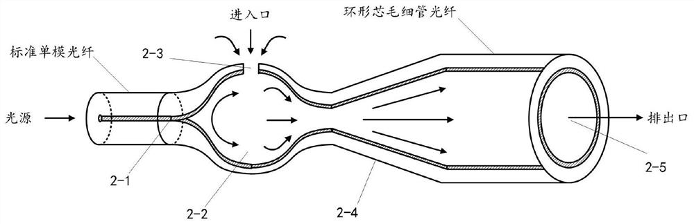
[0053] figure 2 It shows that the ring-core capillary fiber is processed into a jet pump-like structure, wherein one end of the ring-shaped fiber core is melted and shrunk by heating until the capillary pores of the fiber are sealed to form a solid optical wave channel 2-1, thus becoming Optical interface for interconnection with external light sources. After one end is sealed, a nearly spherical heating chamber 2-2 is prepared by means of air pressurization and heating, and a microfluidic liquid microhole is prepared as a liquid inlet 2-3 by using femtosecond drilling processing technology o...


PUM


Abstract

The invention provides a photo-thermal micro-thruster based on annular core capillary optical fiber. The photo-thermal micro-thruster is characterized in that the photo-thermal micro-thruster is composed of a section of annular core capillary optical fiber processed by micromachining, and a light source. The capillary optical fiber is machined into the shape like an injection pump, wherein on endof an annular optical fiber core is thinned through heating and melting to form a solid optical wave channel. After one end is sealed, a subglobular heating chamber is prepared through an air pressurizing and heating method, and a microflow liquid micropore is parpared in the outer surface of the heating chamber through a femtosecond perforating machining technology to serve as a liquid inlet. A Laval nozzle is prepared at an open end through a single-side hot melting tapering method, and the unmachined tail end is an open channel port and is connected with a microflow channel in a micro-fluidic chip needing to be used. The core capillary optical fiber photo-thermal micro-thruster capable of being used for the micro-fluidic chip is easy to prepare, good in consistency, capable of being conveniently embedded in the chip and conveniently and quickly connected with the light source, and suitable for mass production.

Description

[0001] (1) Technical field [0002] The invention relates to a photothermal micro-propeller based on a ring-core capillary optical fiber, which is convenient to be embedded in a microfluidic chip, and can also replace large-scale sampling equipment such as micro-injection pumps and micro-flow peristaltic pumps in the micron-scale operation of micro-liquids. It provides a convenient method for peripheral control equipment of high-throughput analysis and detection of microfluidic chips in the fields of chemistry, biology, medicine, etc., and belongs to the field of optofluidic technology. [0003] (2) Background technology [0004] Microfluidics (Microfluidics or Lab-on-a-chip) refers to a system that uses microchannels of tens of microns or hundreds of microns to process or manipulate tiny fluids. After decades of development, microfluidic technology has become an emerging interdisciplinary subject involving chemistry, fluid physics, optics, microelectronics, new materials, biol...

Claims


Application Information

Patent Timeline
Patent Type & Authority Applications(China)
IPC IPC(8): F04B13/00F04B53/00F04B17/00G02B6/032
CPCF04B13/00F04B53/00F04B17/00G02B6/032
Inventor 苑婷婷张晓彤苑立波
Owner GUILIN UNIV OF ELECTRONIC TECH
Why Eureka
Try Eureka