System capable of utilizing heat conducting oil to recycle waste heat of industrial waste gas

A technology of industrial waste gas and heat transfer oil, which is applied to clean heat transfer devices, lighting and heating equipment, cleaning methods and appliances, etc. It can solve problems such as reducing the heat conversion rate of heat exchange tubes, blocking equipment with impurities, and affecting heat exchange effects. , to achieve the effect of improving the heat transfer effect, improving the heat conversion rate, and improving the removal effect

Active Publication Date: 2020-09-01
四川中电福溪电力开发有限公司
View PDF7 Cites 0 Cited by
  • Summary
  • Abstract
  • Description
  • Claims
  • Application Information

AI Technical Summary

Problems solved by technology

[0005] Aiming at the deficiencies of the existing technology, the purpose of the present invention is to provide a system for recovering waste heat from industrial waste gas by using heat transfer oil, so as to solve the problem of dust or coal ash inside the flue gas when existing equipment recovers waste heat. Timely treatment, impurities will be adsorbed on each pipe inside the equipment, if not treated for a long time, it will cause impurities to block the equipment, general heat exchangers are not easy to remove blockages, impurities are easy to accumulate, which affects

Method used


Image

  • System capable of utilizing heat conducting oil to recycle waste heat of industrial waste gas
  • System capable of utilizing heat conducting oil to recycle waste heat of industrial waste gas
  • System capable of utilizing heat conducting oil to recycle waste heat of industrial waste gas

Examples


Embodiment 1

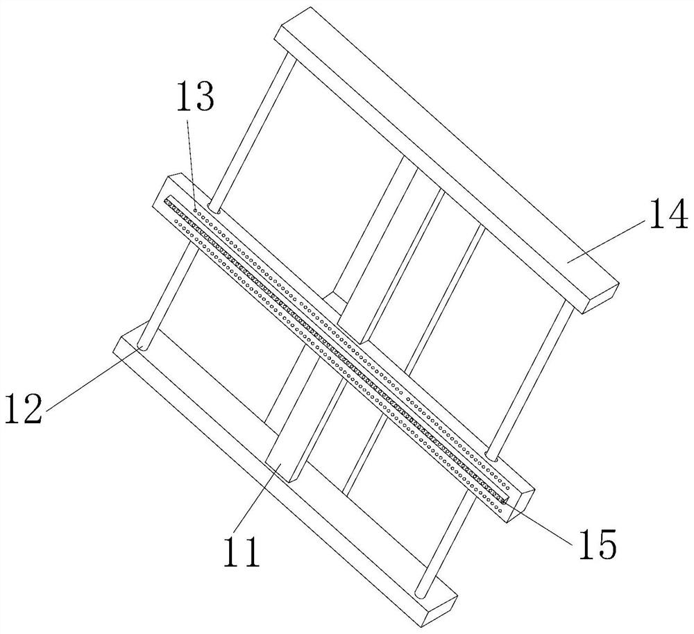
[0032] see figure 1 , the present invention provides a technical solution: a system for recovering waste heat from industrial waste gas by using heat conduction oil, the structure of which includes a soot cleaning device 1, a water inlet pipe 2, an air inlet pipe 3, a preheater 4, a heat exchanger 5, and an air blowing device 6. Outlet pipe 7, connecting pipe 8, circulation pump 9, heat collector 10, the dust removal device 1 is installed on the side of the heat collector 10, the front end of the heat collector 10 is provided with a circulation pump 9, and the circulation The pump 9 is connected through the inside of the heat collector 10, the preheater 4 is arranged at the middle position on the top of the heat collector 10, the preheater 4 is connected with the heat exchanger 5, and the heat exchanger 5 is connected to the right The air blowing device 6 is provided on the side, and the air blowing device 6 is connected to the inside of the heat collector 10, and the top of ...

Embodiment 2

[0039] see figure 1 , the present invention provides a technical solution: a system for recovering waste heat from industrial waste gas by using heat conduction oil, the structure of which includes a soot cleaning device 1, a water inlet pipe 2, an air inlet pipe 3, a preheater 4, a heat exchanger 5, and an air blowing device 6. Outlet pipe 7, connecting pipe 8, circulation pump 9, heat collector 10, the dust removal device 1 is installed on the side of the heat collector 10, the front end of the heat collector 10 is provided with a circulation pump 9, and the circulation The pump 9 is connected through the inside of the heat collector 10, the preheater 4 is arranged at the middle position on the top of the heat collector 10, the preheater 4 is connected with the heat exchanger 5, and the heat exchanger 5 is connected to the right The air blowing device 6 is provided on the side, and the air blowing device 6 is connected to the inside of the heat collector 10, and the top of ...


PUM


Abstract

The invention discloses a system capable of utilizing heat conducting oil to recycle waste heat of industrial waste gas. The system structurally comprises a deashing device, a water intake pipe, an air intake pipe, a preheater, a heat exchanger, a blowing device, a water-out pipe, a connecting pipe, a circulating pump and a heat collector. When the system is used after improvement, a scraper and ascraping and sweeping rod are matched on a support rod to slide left and right so as to rapidly scrape impurities in a waste heat recycling device and prevent the impurities from blocking a waste heat recycling pipeline, and a sliding plate helps the scraping and sweeping rod to move, so that the heat exchanging effect of the waste heat is improved; the blowing component purges viscous dust and very fine dust to blow away dust, so that plenty of dust are prevented from being adsorbed to a heat exchanging pipe; a rotary screw rod drives a disc body to rotate, so that a sweeping brush can rapidly sweep viscous dust and very fine dust in the waste heat recycling device, and then, an adsorption plate adsorbs swept dust, so that the waste heat recycling device can continuously operate to improve the heat conversion rate of the heat exchanging pipe.

Description

technical field [0001] The invention relates to the field of waste heat recovery from waste gas, in particular to a system for recovering waste heat from industrial waste gas by using heat-conducting oil. Background technique [0002] Waste heat recovery refers to the recovery and reuse of waste heat generated in industrial processes. Waste heat resources are secondary energy sources, which are the products of primary energy or combustible material conversion, or the heat emitted during fuel combustion after a certain process is completed. remaining heat. According to the source, industrial waste heat can be divided into: waste heat of flue gas, waste heat of cooling medium, waste heat of waste steam and waste water, heat of chemical reaction, waste heat of high-temperature products and slag, waste heat of combustible waste gas and waste. When recovering waste heat, the areas that need to be improved: [0003] 1. When the existing equipment recovers waste heat, due to the ...

Claims


Application Information

Patent Timeline
IPC IPC(8): F28G1/08F28G3/04F28G13/00B08B7/00
CPCB08B7/00F28G1/08F28G3/04F28G13/00
Inventor 蔡志雄
Owner 四川中电福溪电力开发有限公司
Why Eureka
Try Eureka