
Novel full-automatic carbon forming equipment and working method thereof

A molding equipment, fully automatic technology, applied in the direction of molding pressure head, manufacturing tools, supply devices, etc., can solve the problems of low density of carbon particles, high equipment investment, bulky volume, etc., to achieve high product density and automation High degree of effect with low investment cost

Pending Publication Date: 2020-08-25
SHANDONG SHENGQUAN NEW MATERIALS CO LTD +1
View PDF0 Cites 2 Cited by
  • Summary
  • Abstract
  • Description
  • Claims
  • Application Information

AI Technical Summary

Problems solved by technology

[0003] At present, large-sized carbon blocks are formed by vibration forming machines or hydraulic presses. However, the density of the semi-finished carbon particles processed by the vibration forming machine is low, resulting in the density of the pressed semi-finished products not meeting the requirements. , there are often pores inside the semi-finished product, which eventually leads to a low yield rate of the product
However, the use of hydraulic presses to press has the disadvantages of large volume of mechanical equipment, low production efficiency, high investment in equipment, and relatively low investment in products. Therefore, it is necessary to develop a molding machine with low investment cost, high production efficiency, good product quality, and high degree of automation. machine is very necessary

Method used


Image

  • Novel full-automatic carbon forming equipment and working method thereof
  • Novel full-automatic carbon forming equipment and working method thereof
  • Novel full-automatic carbon forming equipment and working method thereof

Examples


Embodiment Construction

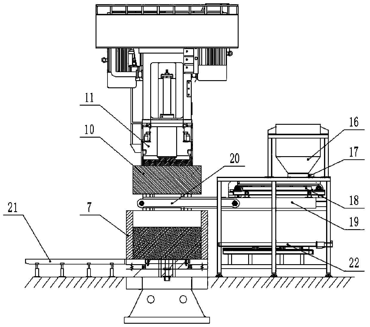
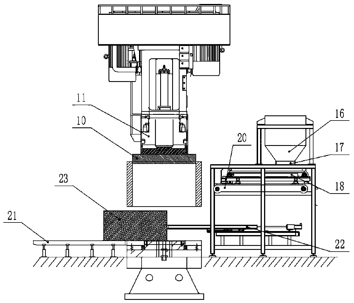
[0045] The present invention will be described in further detail below in conjunction with the accompanying drawings.

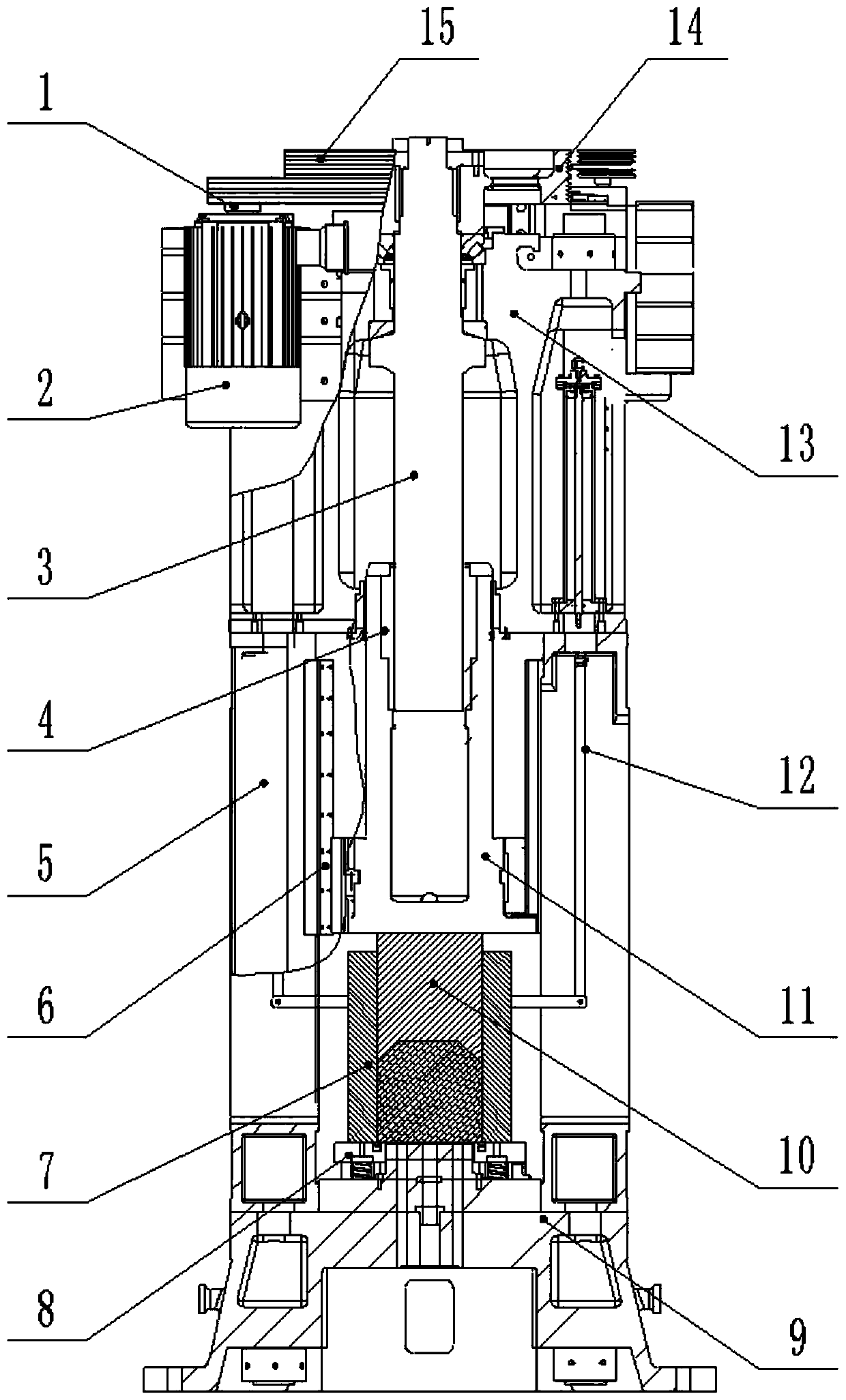
[0046] Such as figure 1 As shown, a new type of fully automatic carbon molding equipment includes a molding machine and an automatic weighing cloth pushing brick machine. The molding machine includes a frame, a large pulley 14, a small pulley 1, a screw 3, a slider 4, and a frame It consists of an upper beam 13, a column 5 and a base 9.

[0047] Drive motor 2 is installed on the upper beam 13, and small pulley 1 is installed on the drive motor 2.

[0048] The screw rod 3 is installed in the upper beam 13 through a thrust bearing and can rotate. The top of the screw rod 3 is equipped with a large pulley 14. The driving motor 2 drives the small pulley 1. The small pulley 1 drives the large pulley 14 through the belt 15 for reciprocating rotation. .

[0049] Large belt pulley 14 is connected with screw rod 3 by positioning pin, drives screw rod 3 to rotate wh...


PUM


Abstract

The invention relates to novel full-automatic carbon forming equipment and a working method thereof. The novel full-automatic carbon forming equipment comprises a forming machine and an automatic weighing, distributing and brick pushing machine, wherein the forming machine comprises a rack, a screw rod rotationally connected with an upper cross beam, a drive motor fixedly connected with the uppercross beam, a sliding block capable of moving up and down along the rack, a nut embedded in the sliding block, an upper hammer installed at the bottom of the sliding block, an elastic workbench installed on a base, and a lower die lifting cylinder installed on the inner side of a stand column; the screw rod is engaged with the nut through a thread, a lower die falls on the elastic workbench, and the lower end of the lower die lifting cylinder is connected with the lower die; and the automatic weighing, distributing and brick pushing machine comprises an electric gate arranged on the lower portion of a temporary storage bin and used for controlling the raw material supply process, a belt weigher arranged on the lower portion of the electric gate and provided with a weighing sensor, and a distributing belt used for conveying materials of the belt weigher. The full-automatic forming equipment is high in automation degree, high in product forming body density, low in investment cost and high in production efficiency.

Description

technical field [0001] The invention relates to the technical field of carbon processing equipment, in particular to a novel fully automatic carbon forming equipment and a working method thereof. Background technique [0002] The current molding process of carbon products is to mix carbon powder, aggregate, binder and other raw materials, and then use mechanical equipment to pressurize them into products of the desired shape, so that the products have a higher density. [0003] At present, large-sized carbon blocks are formed by vibration forming machines or hydraulic presses. However, the density of the semi-finished carbon particles processed by the vibration forming machine is low, resulting in the density of the pressed semi-finished products not meeting the requirements. , There are often pores inside the semi-finished product, which eventually leads to a low yield rate of the product. However, the use of hydraulic presses to press has the disadvantages of large volume...

Claims


Application Information

Patent Timeline
IPC IPC(8): B28B3/04B28B13/02
CPCB28B3/04B28B13/02
Inventor 田江涛王程邱同昌郭小红
Owner SHANDONG SHENGQUAN NEW MATERIALS CO LTD
Learn More