
Heating device and method for large-diameter thick-wall pipe

A technology of a heating device and a heating method, which is applied in the field of pipe bending, can solve the problems that the circumferential deformation of the steel pipe is not considered, and the quality of the pipe blank is difficult to be effectively solved, so as to achieve the effect of optimizing the distribution of the temperature field and improving the quality

Active Publication Date: 2020-08-25
江苏鲁宁管业科技有限公司
View PDF9 Cites 0 Cited by
  • Summary
  • Abstract
  • Description
  • Claims
  • Application Information

AI Technical Summary

Problems solved by technology

[0004] The Chinese patent with the publication number CN106140907A discloses a double-temperature simmering method for high-grade steel induction heating elbows. This method adjusts the local gap of the induction coil and places the weld seam of the steel pipe at the position after the gap is adjusted, so as to achieve the steel pipe in the During the heating process, the temperature of the weld position is different from that of other positions to achieve double-temperature simmering. However, this method does not consider the difference in the circumferential deformation of the steel pipe during the bending process. Except for the weld position, the others are all heated to the same temperature. The quality problem of the tube billet after bending caused by the difference in deformation is still difficult to be effectively solved

Method used


Image

  • Heating device and method for large-diameter thick-wall pipe
  • Heating device and method for large-diameter thick-wall pipe
  • Heating device and method for large-diameter thick-wall pipe

Examples


Embodiment Construction

[0040] In order to detail the technical content, structural features, achieved goals and effects of the present invention, the following will be described in detail in conjunction with the accompanying drawings.

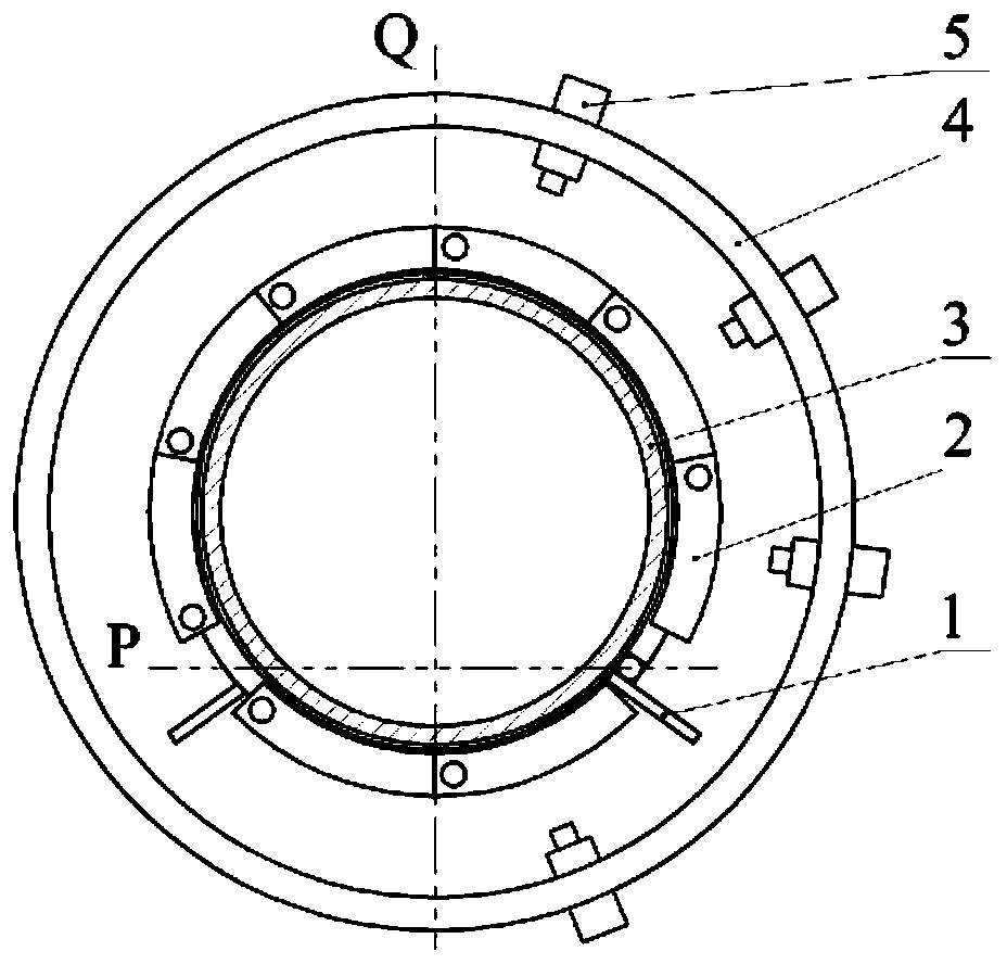
[0041] Heating devices for large-diameter thick-walled pipes, such as figure 1 As shown, it includes an induction coil 1 , a magnetizer 2 , a target tube blank 3 , a bracket 4 , an infrared thermometer 5 and a liquid pressure controller 7 .

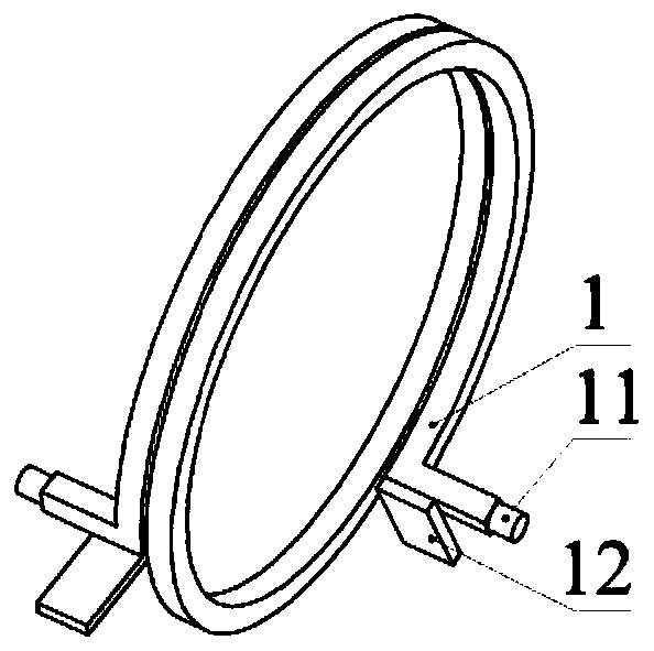
[0042] Such as figure 2As shown, the shape of the induction coil 1 is a spiral structure wound by a rectangular hollow copper tube, and the outer surface is coated with an insulating layer. The two ends of the induction coil 1 are respectively provided with a water inlet and outlet 11 and a terminal block 12. The water inlet and outlet 11 are used for The induction coil 1 is cooled by cooling water during the working process, and the terminal board 12 is used for connecting an external power supply. The diameter of the helix ...


PUM


Abstract

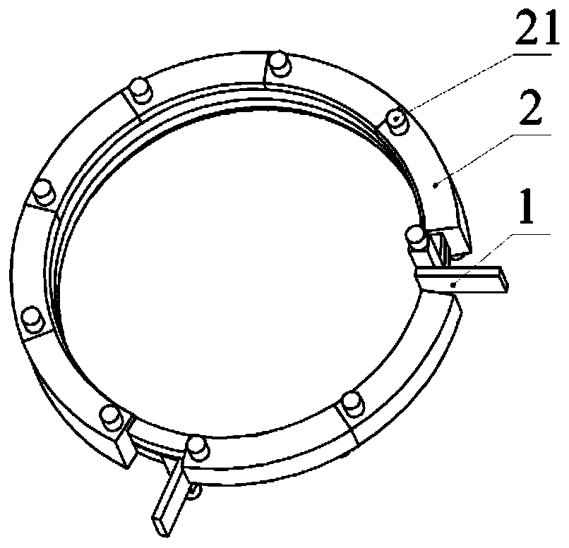
The invention provides a heating device for a large-diameter thick-wall pipe. The heating device comprises an induction coil, magnetizers, an infrared temperature measuring instrument and a liquid pressure controller. The appearance of the induction coil is of a spiral structure formed through winding of a rectangular hollow copper pipe. The two ends of the induction coil are provided with a waterinlet and outlet port and a wiring board correspondingly. The appearance of each magnetizer is of a saddle-shaped hollow structure. The inner surface of each magnetizer groove wraps the induction coil. A water inlet and a water outlet are formed in the two sides of the outer surface of each magnetizer correspondingly, wherein the water inlet is connected with the liquid pressure controller. A support is connected with the infrared temperature measuring instrument. A neutral layer is a face P when a target pipe blank is bent, the induction coil is divided into a small-turn-number end and a large-turn-number end through the face P, and the small-turn-number end and the large-turn-number end are located on the bent inner side and the bent outer side of the target pipe blank correspondingly.The character that the magnetism conduction capability of the magnetizers changes along with the temperature is utilized, through the symmetrically-arranged magnetizers, temperature field distributionafter pipe blank heating is optimized, and the quality after pipe blank bending is effectively improved.

Description

technical field [0001] The invention relates to the field of pipe bending processing, in particular to a heating device and a heating method for large-diameter thick-walled pipes. Background technique [0002] The bending processing of pipes occupies an important position in industrial sectors such as metal structure, engineering machinery, petrochemical industry, light industry, etc. Among them, large-diameter thick-walled pipes are widely used in gas and liquid transportation networks. The intermediate frequency induction local heating pipe bending process is the most advanced process method in the large diameter thick wall pipe bending processing. The intermediate frequency induction heating equipment is used to locally heat the tube blank to the required temperature, and then the heated part is bent to obtain the target Bend fittings. [0003] Precise control of the heating temperature during the tube blank forming is one of the research focuses of the intermediate freq...

Claims


Application Information

Patent Timeline
IPC IPC(8): B21D7/16B21D9/18B21D37/16
CPCB21D7/162B21D9/18B21D37/16
Inventor 于恩林卢轩
Owner 江苏鲁宁管业科技有限公司
Learn More