


Quick Research
Generate reliable direction feasibility study reports for your R&D in just a few steps.

Technical Q&A
Discover and master advanced knowledge NOW. Basics, ideas, possibilities, all at once.

Find Solutions
As an expert in R&D theories, this can generate solutions to your technical problems instantly.

Evaluate Feasibility
Analyze your overall solution with one click, know your potential R&D risks in advance.

Monitor Landscape
Get weekly tech updates, stay abreast of the latest tech innovations and key insights.
Wet desulfurization system and wet desulfurization method
A wet desulfurization and desulfurization tower technology, applied in the field of desulfurization, can solve the problems of easily breaking the water balance of the desulfurization system, waste of thermal energy and water resources, and the burden of large desulfurization wastewater treatment, so as to achieve the removal of small pollutants and the reduction of desulfurization wastewater. The effect of exhausting and eliminating the phenomenon of white smoke
- Summary
- Abstract
- Description
- Claims
- Application Information
AI Technical Summary
Problems solved by technology
Method used
Image

Examples
Embodiment 1
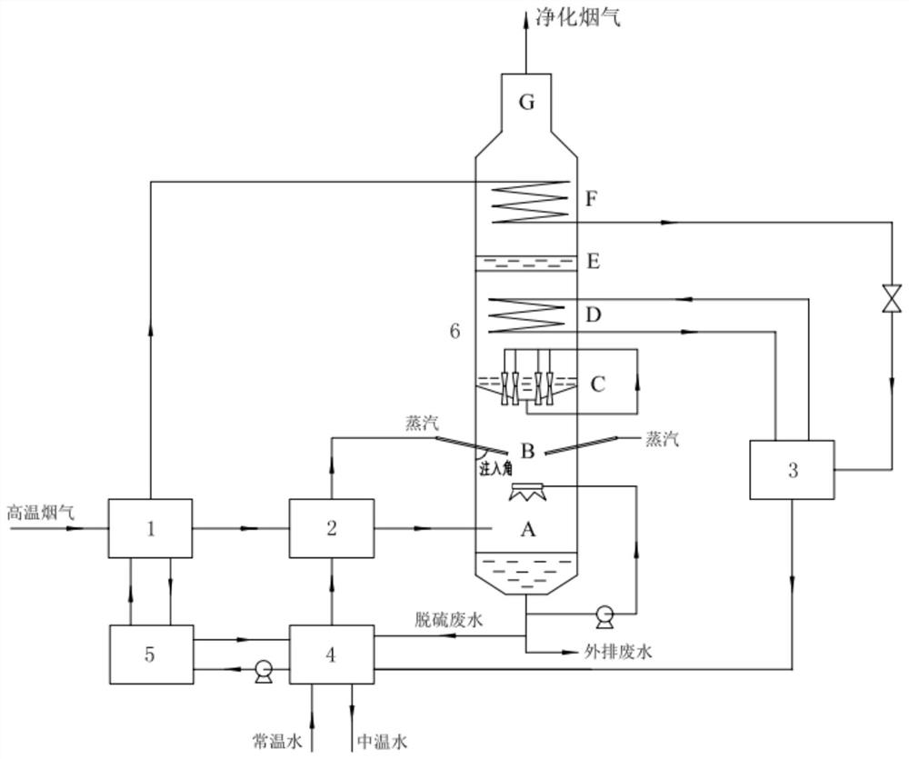
[0041] See attached figure 1, this embodiment provides a wet desulfurization system, which includes a desulfurization tower 6 and a split heat pump system. The interior of the desulfurization tower 6 includes a cooling absorption section A, a steam injection section B, and a spray washing section C from bottom to top. , deep cooling section D, demisting section E, flue gas heating section F and flue gas outlet section G. The split heat pump system includes a generator 1, a waste water evaporator 2, a cryogenic evaporator 3, an absorber 4, a heat exchanger 5, and a sulfur-containing flue gas inlet pipe connected to the cooling absorption section A of the desulfurization tower 6.
[0042] It should be noted that, in other embodiments, the spray washing section C or the demisting section E may be omitted as required.
[0043] A generator 1 and a waste water evaporator 2 are arranged in sequence along the flow direction of the sulfur-containing flue gas inlet pipe. The generator ...
Embodiment 2
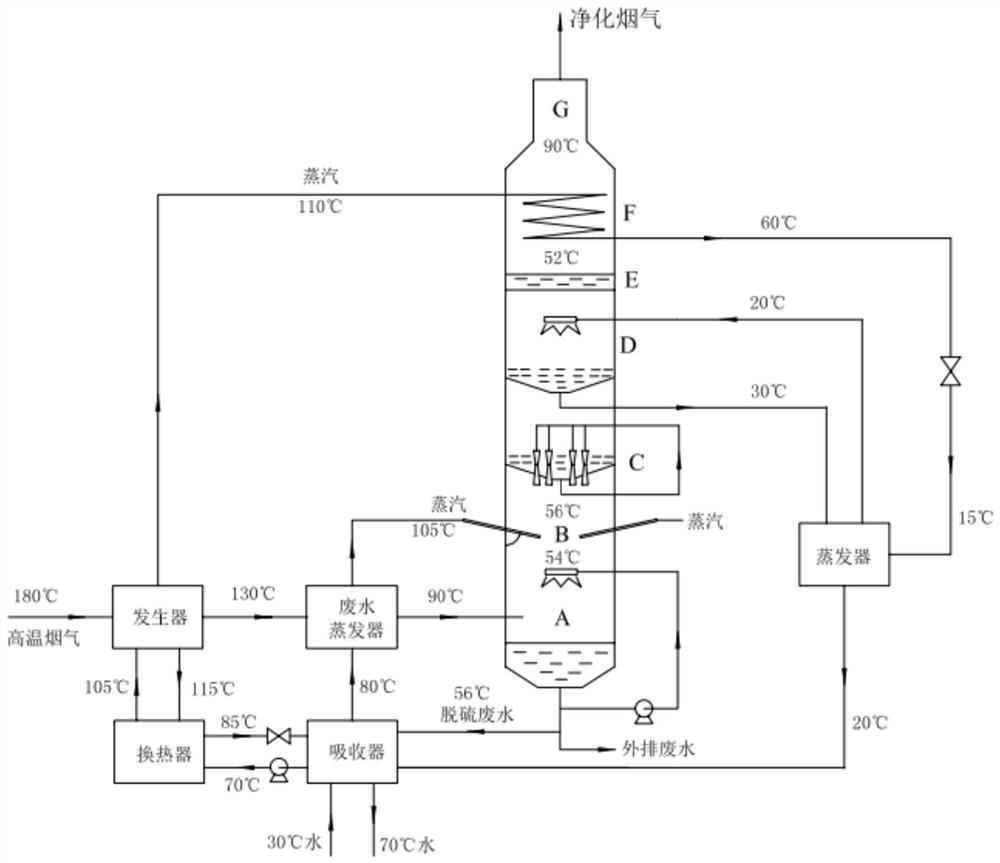
[0062] This embodiment also provides a specific wet desulfurization method using the wet desulfurization system of Embodiment 1.
[0063] See attached figure 2 , the steam injection section B of the desulfurization tower of the wet desulfurization system has two steam injection ports, and the injection angle between the steam injection direction and the wall of the desulfurization tower is 30°. The deep cooling water and flue gas in the deep cooling section can adopt the direct contact spray heat exchange type; the refrigerant liquid is lithium bromide solution; the demister of the demisting section E of the desulfurization tower is a baffle demister. in, figure 2 The evaporator in is a deep cooling evaporator.
[0064] The 180°C high-temperature flue gas from the waste heat boiler enters the generator, and enters the waste water evaporator after the temperature drops to 130°C. After evaporating the waste water, the flue gas temperature drops to 90°C and enters the desulfu...
PUM
 Abstract
Description
Claims
Application Information
 - R&D Engineer
- R&D Manager
- IP Professional
- Industry Leading Data Capabilities
- Powerful AI technology
- Patent DNA Extraction
Browse by: Latest US Patents, China's latest patents, Technical Efficacy Thesaurus, Application Domain, Technology Topic, Popular Technical Reports.
© 2024 PatSnap. All rights reserved.Legal|Privacy policy|Modern Slavery Act Transparency Statement|Sitemap|About US| Contact US: help@patsnap.com