
Wet desulfurization system and wet desulfurization method

A wet desulfurization and desulfurization tower technology, applied in the desulfurization field, can solve the problems of easily breaking the water balance of the desulfurization system, the burden of large desulfurization wastewater treatment, waste of thermal energy and water resources, etc., and achieves the removal of fine pollutants and white smoke. Phenomenon, effect of desulfurization wastewater emission reduction

Active Publication Date: 2020-08-25
CHINA PETROLEUM & CHEM CORP +1
View PDF12 Cites 1 Cited by
  • Summary
  • Abstract
  • Description
  • Claims
  • Application Information

AI Technical Summary

Problems solved by technology

This method relies on injecting cooling water to establish a supersaturated environment, the water consumption of the system is large, the corresponding desulfurization wastewater treatment volume increases significantly, the operating cost of the desulfurization system is high, and this method is easy to break the water balance of the desulfurization system and affect the overall desulfurization efficiency.
[0005] In addition, the above desulfurization methods will also produce a large amount of white smoke after being discharged into the air. In the case of wasting a lot of heat energy and water resources, it will cause strong visual pollution and cause a large burden on desulfurization wastewater treatment.

Method used


Image

  • Wet desulfurization system and wet desulfurization method
  • Wet desulfurization system and wet desulfurization method

Examples


Embodiment 1

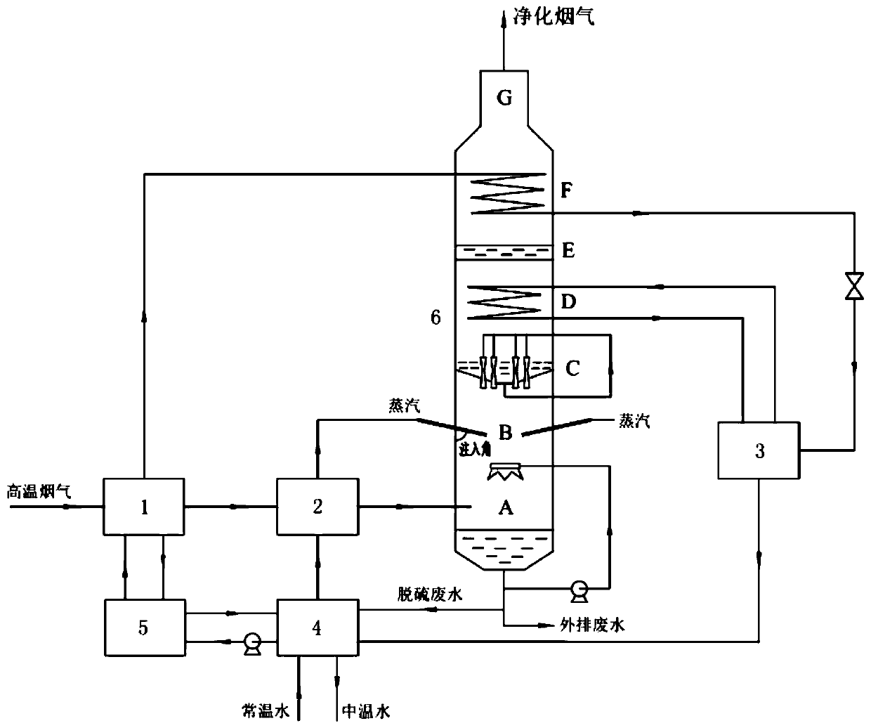
[0041] See attached figure 1, this embodiment provides a wet desulfurization system, which includes a desulfurization tower 6 and a split heat pump system. The interior of the desulfurization tower 6 includes a cooling absorption section A, a steam injection section B, and a spray washing section C from bottom to top. , deep cooling section D, demisting section E, flue gas heating section F and flue gas outlet section G. The split heat pump system includes a generator 1, a waste water evaporator 2, a cryogenic evaporator 3, an absorber 4, a heat exchanger 5, and a sulfur-containing flue gas inlet pipe connected to the cooling absorption section A of the desulfurization tower 6.

[0042] It should be noted that, in other embodiments, the spray washing section C or the demisting section E may be omitted as required.

[0043] A generator 1 and a waste water evaporator 2 are arranged in sequence along the flow direction of the sulfur-containing flue gas inlet pipe. The generator ...

Embodiment 2

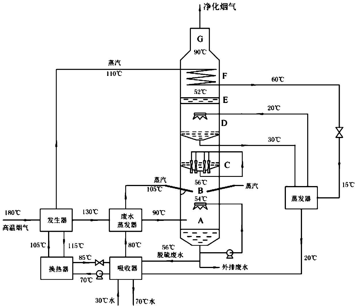
[0062] This embodiment also provides a specific wet desulfurization method using the wet desulfurization system of Embodiment 1.

[0063] See attached figure 2 , the steam injection section B of the desulfurization tower of the wet desulfurization system has two steam injection ports, and the injection angle between the steam injection direction and the wall of the desulfurization tower is 30°. The deep cooling water and flue gas in the deep cooling section can adopt the direct contact spray heat exchange type; the refrigerant liquid is lithium bromide solution; the demister of the demisting section E of the desulfurization tower is a baffle demister. in, figure 2 The evaporator in is a deep cooling evaporator.

[0064] The 180°C high-temperature flue gas from the waste heat boiler enters the generator, and enters the waste water evaporator after the temperature drops to 130°C. After evaporating the waste water, the flue gas temperature drops to 90°C and enters the desulfu...


PUM


Abstract

The invention discloses a wet desulfurization system and a wet desulfurization method. According to the invention, a generator and a wastewater evaporator are arranged in a split heat pump system to continuously reduce the temperature of sulfur-containing flue gas introduced into a desulfurization tower to an acid dew point temperature or below so as to promote the condensation of SO3 in the fluegas and the primary growth of fine pollutants; sulfur-containing flue gas is utilized to evaporate desulfurization wastewater in the wastewater evaporator, so water vapor is generated and is injectedinto the desulfurization tower, a supersaturated water vapor environment is established, and fine pollutants in the desulfurization flue gas are promoted to grow large for the second time; and meanwhile, a certain amount of cold and heat are produced through the generator and a deep evaporator, the cold is used for deep cooling of purified flue gas, constructing a supersaturated water vapor environment and promote third-time growth of fine pollutants, and the heat is used for heating the purified flue gas of the desulfurization tower so as to increase the temperature of the purified flue gas and eliminate a white smoke phenomenon. Thus, the purposes of removal of small pollutants in desulfurized flue gas, elimination of white smoke and emission reduction of desulfurized wastewater are achieved.

Description

technical field [0001] The invention relates to the technical field of desulfurization, in particular to a wet desulfurization system and a wet desulfurization method. Background technique [0002] The flue gas generated by the combustion of boilers, incinerators, catalytic cracking units, etc. needs to be desulfurized before being discharged into the atmosphere. Generally, wet desulfurization is used to treat sulfur-containing flue gas. At present, the purified flue gas after desulfurization still contains a large amount of submicron SO 3 Fog droplets, fine particles, volatile salts and other pollutants are discharged into the atmosphere to form smog weather, which seriously affects the visibility of the surrounding environment and the physical and mental health of residents. The removal efficiency of sub-micron fine pollutants in the desulfurization flue gas is low in the wet desulfurization system, and the removal efficiency generally does not exceed 40%. [0003] For t...

Claims


Application Information

Patent Timeline
IPC IPC(8): B01D53/78B01D53/50B01D5/00B01D53/00B01D47/06
CPCB01D53/78B01D53/50B01D47/06B01D53/002B01D2258/0283
Inventor 李玖重孙志钦李国智周天宇高晓红郜建松张婧帆高跃成
Owner CHINA PETROLEUM & CHEM CORP
Learn More