
Charge arrangement device applied to probe station

A technology of probe station and charge, which is applied in the direction of measuring devices, measuring electricity, and measuring electrical variables, etc., can solve problems such as leakage, inaccurate data, and damaged components, so as to reduce leakage loss, ensure accuracy, and reduce parasitic The effect of capacitance

Pending Publication Date: 2020-08-18
苏州伊欧陆系统集成有限公司
View PDF0 Cites 0 Cited by
  • Summary
  • Abstract
  • Description
  • Claims
  • Application Information

AI Technical Summary

Problems solved by technology

[0015] The purpose of the present invention is to overcome the defects in the prior art that the potential of each part of the probe station is in a floating state, and there are gaps in the "Faraday cage" charge arrangement during the test process, which makes the data inaccurate or damages the components. A "Faraday cage" type charge arrangement device that has no gaps and prevents current signal leakage and is applied to a probe station

Method used


Image

  • Charge arrangement device applied to probe station
  • Charge arrangement device applied to probe station
  • Charge arrangement device applied to probe station

Examples


Embodiment Construction

[0039] The present invention is described in further detail now in conjunction with accompanying drawing. These drawings are all simplified schematic diagrams, and only illustrate the basic structure of the present invention in a schematic manner, so they only show the configurations related to the present invention.

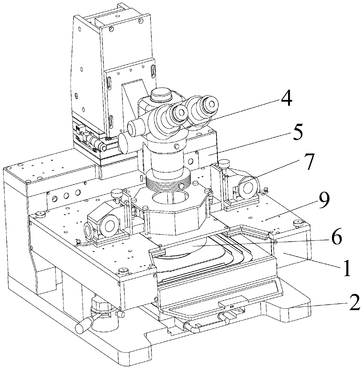
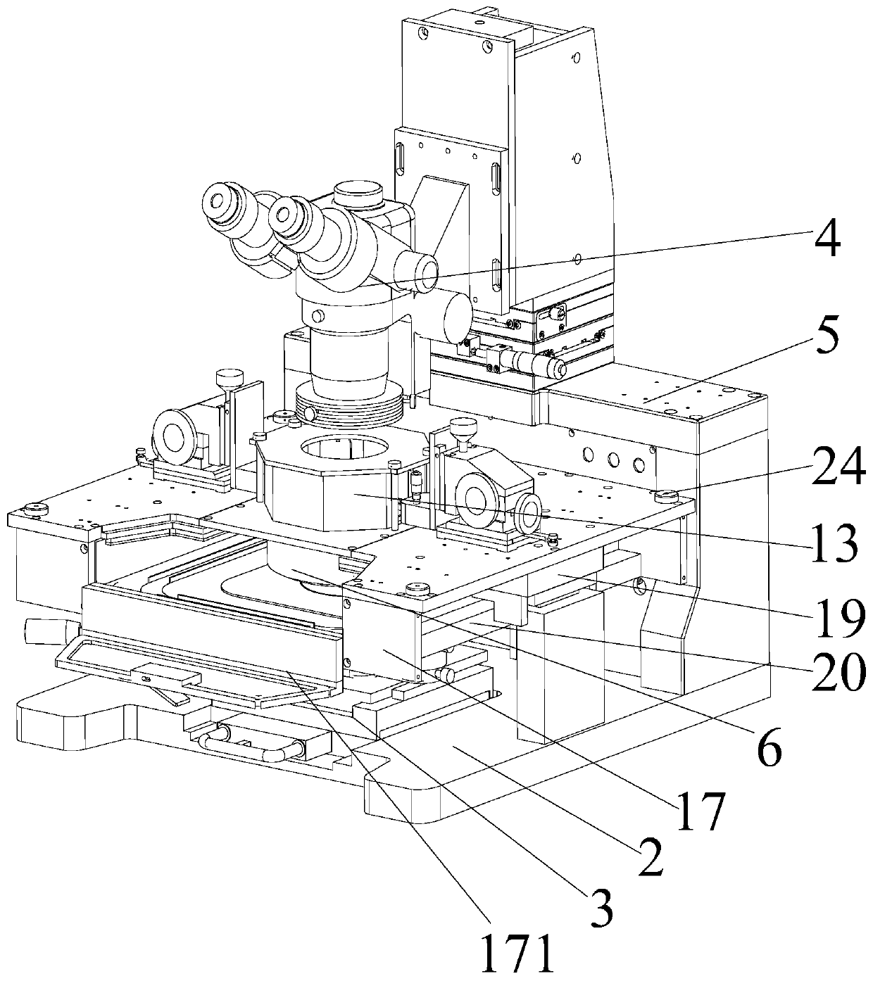
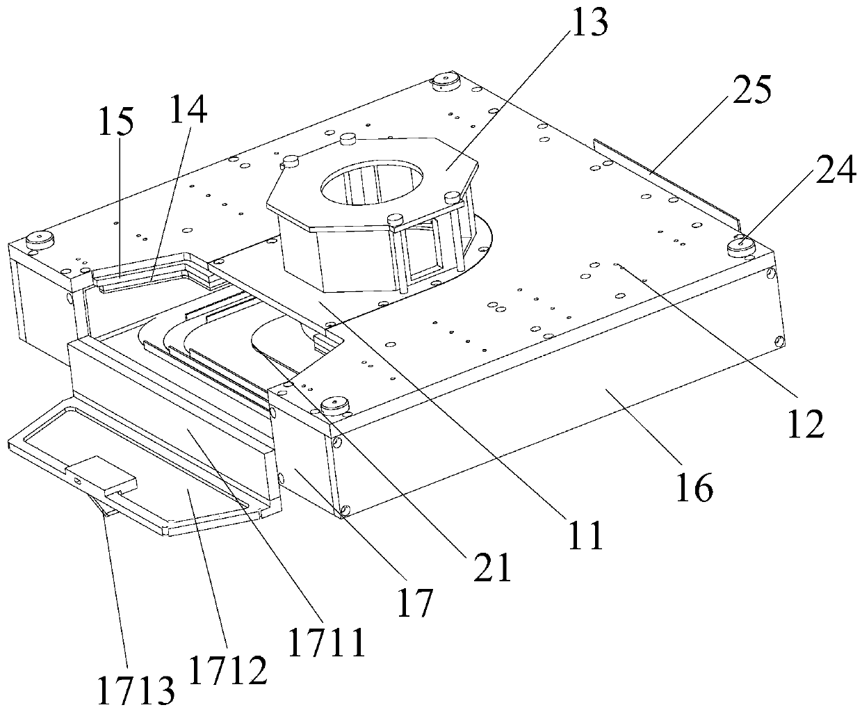
[0040] Such as Figure 1-Figure 5 Shown is a specific embodiment of a charge arrangement device applied to a probe station of the present invention, the charge arrangement device 1 is arranged between the base 2 of the probe station and the microscope 4, and is characterized in that: The plate 11 is fixed on the probe platform 12, and the sealing top cover 13 with positioning through holes is opened on the left and right sides, the protective layer 14 arranged on the probe platform 12, the protective layer 14 arranged between the probe platform 12 and the protective layer 14 Insulation layer 15, side plates 16 fixed on the left and right sides of the probe plat...


PUM


Abstract

The invention belongs to the technical field of semiconductor test equipment, and particularly relates to a charge arrangement device applied to a probe station. The charge arrangement device includes: a sealing top cover which is fixed on a probe platform through a connecting plate, wherein positioning through holes are formed in the left side and the right side of the sealing top cover; a protective layer which is arranged on the probe platform; an insulating layerwhich is arranged between the probe platform and the protective layer; side plates which are fixed to the left side and the right side of the probe platform; a front plate and a rear plate which are fixed to the front end and the rear end of the probe platform; a supporting framework which is fixed to the probe station base through supporting cushion blocks; and a sliding bottom plate assembly which is clamped on the supporting framework. An objective table of the probe platform penetrates through the sliding bottom plateassembly and is rotationally connected to the probe platform base. By managing the charge arrangement structure, a test object is located in a Faraday cage cavity, and by managing the potential arrangement of each structure of the probe station, the occurrence of factors such as parasitic capacitance, common-mode voltage, grounding loop current and the like which are not beneficial to integrated circuit test is reduced, so that the test capability of the probe station is improved.

Description

technical field [0001] The invention belongs to the technical field of semiconductor testing equipment, and in particular relates to a charge arrangement device applied to a probe station. Background technique [0002] Probe stations are testing equipment used in the semiconductor industry, especially in the field of integrated circuit testing, and are widely used. Usually, the integrated circuit will be tested for electrical performance on the probe station to determine whether the integrated circuit meets the design requirements or meets the use requirements. With the advancement of technology and the improvement of demand, the integrated circuit manufacturing process is becoming more and more advanced, the performance is getting higher and higher, and the corresponding testing requirements and testing environment are becoming more and more stringent. This also puts forward higher requirements for the probe station, which not only requires more precise movement accuracy, ...

Claims


Application Information

Patent Timeline
Patent Type & Authority Applications(China)
IPC IPC(8): G01R31/28G01R1/02
CPCG01R1/02G01R31/2868G01R31/2879G01R31/2886
Inventor 刘伟张海洋吕文波
Owner 苏州伊欧陆系统集成有限公司
Learn More