
Ultra-low temperature ball valve seat machining device

A machining, ultra-low temperature technology, applied in the field of seal processing, can solve the problems of poor ball valve seat locking stability, cumbersome ball valve locking steps, poor valve seat cutting accuracy, etc., to achieve simple and fast locking operation, increase stability, and increase cutting The effect of precision

Active Publication Date: 2020-08-18
JIANG SU YAN DIAN FA MEN CO LTD
View PDF7 Cites 12 Cited by
  • Summary
  • Abstract
  • Description
  • Claims
  • Application Information

AI Technical Summary

Problems solved by technology

[0004] 1. There is no locking fixture for the seat structure when the ball valve seat is cut and locked, and there is a certain deviation between the locked center position of the ball valve seat and the center position of the rotating shaft, resulting in poor cutting accuracy of the valve seat;
[0005] 2. The locking stability of the ball valve seat is poor, which causes a certain degree of displacement and rotation of the valve seat when it is cut and processed. The locking steps of the ball valve are relatively cumbersome, resulting in low processing efficiency of the ball valve.

Method used


Image

  • Ultra-low temperature ball valve seat machining device
  • Ultra-low temperature ball valve seat machining device
  • Ultra-low temperature ball valve seat machining device

Examples


Embodiment Construction

[0030] In order to make the technical means, creative features, goals and effects achieved by the present invention easy to understand, the present invention will be further described below in conjunction with specific illustrations. It should be noted that, in the case of no conflict, the embodiments in the present application and the features in the embodiments can be combined with each other.

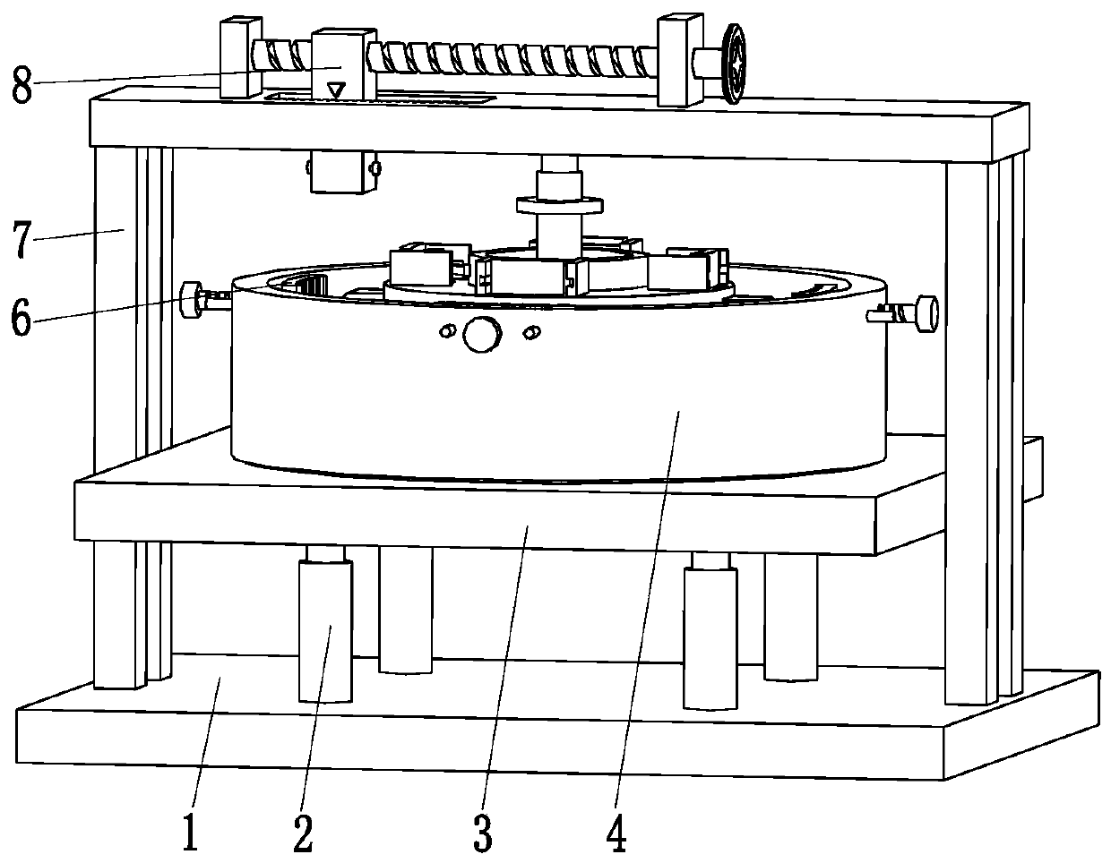
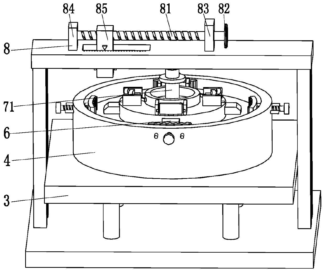
[0031] Such as Figure 1 to Figure 7As shown, a machining device for an ultra-low temperature ball valve seat includes a bottom plate 1, a cylinder 2, a lifting platform 3, a placement frame 4, a rotating motor 5, a locking mechanism 6, a moving frame 7, and a moving mechanism 8. The top of the bottom plate 1 The lifting platform 3 is installed through the cylinder 2, and the middle part of the lifting platform 3 is provided with an annular chute. The cross section of the annular chute is a T-shaped structure. The frame 4 is a hollow cylinder structure with an open lower end. The to...


PUM


Abstract

The invention relates to an ultra-low temperature ball valve seat machining device. The ultra-low temperature ball valve seat machining device comprises a bottom plate, a cylinder, a lifting table, aplacing frame, a rotating motor, a locking mechanism, a moving frame and a moving mechanism. The lifting table is installed at the top of the bottom plate through the cylinder, a ring chute is formedin the middle part of the lifting table, and the lower end of the placing frame is connected with the ring chute in a sliding fit mode. The lower end of the placing frame is of a hollow cylinder structure with an opening, an output shaft of the rotating motor is connected with the middle and lower side wall of the placing frame, the locking mechanism is installed on the placing frame, the lower end of the moving frame is connected with the top of the bottom plate, and the moving mechanism is installed on the moving frame. The ultra-low temperature ball valve seat machining device can solve theexisting problems that when an existing ball valve seat is cut and machined, no locking fixture is provided for a valve seat structure during cutting and locking of a ball valve seat, a certain deviation exists between the center position of the ball valve seat after locking and the center position of a rotating shaft, so that the cutting accuracy of the valve seat is poor.

Description

technical field [0001] The invention relates to the field of sealing member processing, in particular to a machining device for an ultra-low temperature ball valve seat. Background technique [0002] As an emerging clean energy, liquefied natural gas has been widely used. The temperature of liquefied natural gas under standard pressure is -162°C, which is an ultra-low temperature environment in the field of valves; the valve is used as a supporting facility for liquefied natural gas transfer and storage equipment, and its usage is increasing year by year. [0003] The valve seat on the ultra-low temperature ball valve plays a role in sealing. The processing accuracy of the ball valve seat directly affects the sealing performance of the ball valve. The ball valve seat is a ring structure, and its inner surface is a wedge-shaped structure. The annular groove for installing the sealing ring, the wedge-shaped structure of the ball valve seat and the annular groove are formed by...

Claims


Application Information

Patent Timeline
Patent Type & Authority Applications(China)
IPC IPC(8): B23D79/00B23Q3/06B23Q1/46B23Q5/10B23Q5/26
CPCB23D79/00B23Q1/46B23Q3/062B23Q5/10B23Q5/26
Inventor 侯勇俊孔祥伟叶小华文昌明孙德林康邦华
Owner JIANG SU YAN DIAN FA MEN CO LTD
Learn More