A positioning method and a processing method for an aircraft skin assembly hole
A technology of aircraft skinning and positioning method, which is applied in the direction of metal processing equipment, metal processing machine parts, manufacturing tools, etc. It can solve the problems of poor efficiency of manual marking, frequent design changes, and long change cycle, so as to reduce the difficulty of design, Improve display clarity, reduce design difficulty and cost
- Summary
- Abstract
- Description
- Claims
- Application Information
AI Technical Summary
Problems solved by technology
Method used
Image

Examples
Embodiment 1
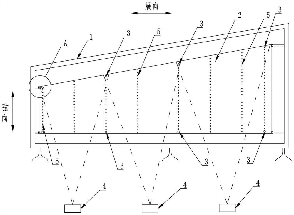
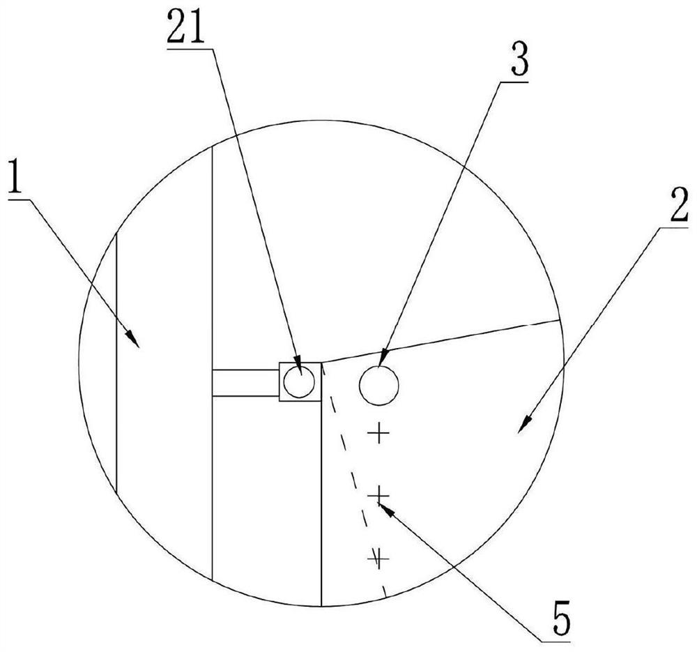
[0037] see figure 1 As shown, the positioning method of the aircraft skin assembly hole provided by the embodiment of the present invention, the chordwise length of the aircraft skin is 2m, the spanwise length is 10m, and a fixing hole 21 is respectively set at the corners of the aircraft skin 2, totally four The four fixing holes 21 are used to install the aircraft skin 2 on the assembly frame 1 through the four fixing holes 21 . A positioning hole is respectively set at the assembly holes of the four corners of the aircraft skin 2 and the internal rib and the beam, four positioning holes are arranged at the center of the aircraft skin, and the target 3 is set at the eight positioning holes. The eight targets 3 realize the connection of the spatial position of the aircraft skin 2 with the laser projection system. The position coordinates of the target 3 are collected, and a projection file is prepared by using a computer according to the position coordinates of the target 3,...
Embodiment 2
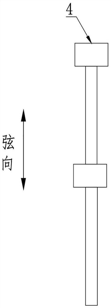
[0052] The second embodiment is basically the same as the first embodiment, and the similarities will not be described in detail. The difference is that the aircraft skin has a chord length of 6m and a span length of 15m, at the four corners of the aircraft skin 2 and the internal ribs and beams. One positioning hole is arranged at each assembly hole of the aircraft skin 2, and eleven positioning holes are arranged in the center of the aircraft skin 2. Targets 3 are set at the fifteen positioning holes, and the aircraft skin 2 is realized through the fifteen targets 3. The spatial location is connected with the laser projection system. For an aircraft skin of this size class, the laser projection system consists of eight laser projectors 4, see image 3 As shown, eight laser projectors 4 are arranged in two rows in the chord upward, and the number of laser projectors 4 in each row is the same as four, and each row of laser projectors 4 is arranged at equal intervals to realize...
Embodiment 3
[0056] Present embodiment three is basically the same as embodiment one, and the similarities will not be described in detail. The difference is that the aircraft skin 2 has a chord length of 2m and a span length of 6m. One positioning hole is set at each assembly hole in the corner, two positioning holes are arranged in the center of the aircraft skin, and targets 3 are set at the six positioning holes, and the spatial position of the aircraft skin 2 is realized through the six targets 3 Interface with laser projection system. For the aircraft skin 2 of this size class, the laser projection system includes two laser projectors 4, and the two laser projectors 4 are arranged at equidistant intervals and arranged in a row.
PUM
| Property | Measurement | Unit |
|---|---|---|
| length | aaaaa | aaaaa |
| thickness | aaaaa | aaaaa |
| length | aaaaa | aaaaa |
Abstract
Description
Claims
Application Information
 - Generate Ideas
- Intellectual Property
- Life Sciences
- Materials
- Tech Scout
- Unparalleled Data Quality
- Higher Quality Content
- 60% Fewer Hallucinations
Browse by: Latest US Patents, China's latest patents, Technical Efficacy Thesaurus, Application Domain, Technology Topic, Popular Technical Reports.
© 2025 PatSnap. All rights reserved.Legal|Privacy policy|Modern Slavery Act Transparency Statement|Sitemap|About US| Contact US: help@patsnap.com