Eureka AIR delivers breakthrough ideas for toughest innovation challenges, trusted by R&D personnel around the world.

Ion exchange desulfurization and denitrification integrated process and equipment

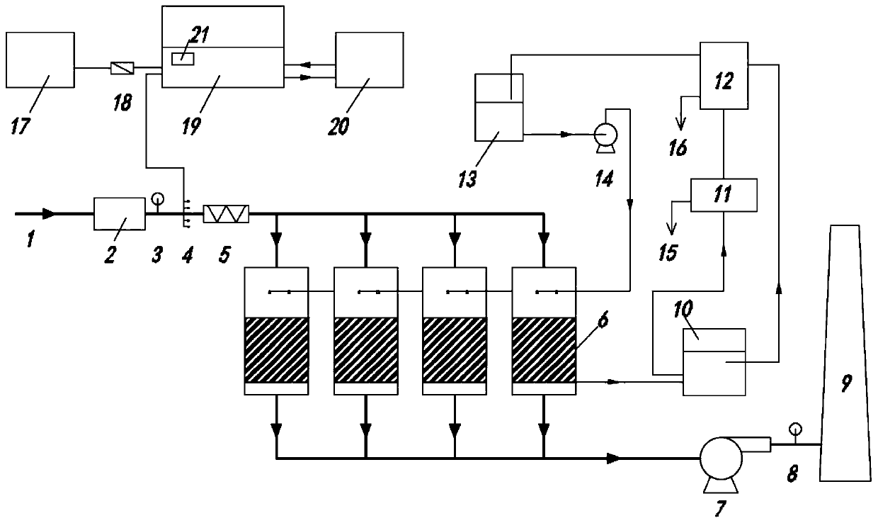
An ion exchange method, desulfurization and denitrification technology, applied in the field of ion exchange desulfurization and denitrification integrated process and equipment, can solve the problems of non-specially designed absorption process devices, high cost of harmless treatment, increased toxicity of pollutants, etc., to achieve regulation Rich means, solving the problem of yellow smoke, and the effect of saving ozone consumption

Pending Publication Date: 2020-08-07
BEIJING JINGDAWANXIANG ENVIRONMENTAL PROTECTION CO LTD +1
View PDF0 Cites 2 Cited by
  • Summary
  • Abstract
  • Description
  • Claims
  • Application Information

AI Technical Summary

Problems solved by technology

[0005] Ozone oxidation flue gas denitrification technology often encounters the following problems in engineering applications: (1) Difficulties in disposal of generated wastewater and waste residues
Absorbing nitrogen oxides by a wet method will produce a large amount of waste liquid, and absorbing nitrogen oxides by a semi-dry method will produce a large amount of waste ash and residue. The amount of waste water and residue is large, the cost of harmless treatment is high, and resource utilization is difficult.
(2) The dosage of ozone is large and the cost is high
In order to achieve a high denitrification rate, it is necessary to greatly increase the excess ozone to generate more nitrogen pentoxide, which reduces the economy and may cause the remaining ozone to exceed the standard
(3) Yellow smoke phenomenon
If the absorption process cannot catch up with the oxidation process, the nitrogen dioxide produced will be emitted before being absorbed, yellow smoke will appear, and the toxicity of pollutants will increase.
The main problem is that the absorption process unit in many projects is not specially designed

Method used


Image

  • Ion exchange desulfurization and denitrification integrated process and equipment
  • Ion exchange desulfurization and denitrification integrated process and equipment
  • Ion exchange desulfurization and denitrification integrated process and equipment

Examples


Embodiment Construction

[0028] The specific embodiments of the present invention will be further described below in conjunction with the accompanying drawings. It should be noted here that the descriptions of these embodiments are used to help understand the present invention, but are not intended to limit the present invention. In addition, the technical features involved in the various embodiments of the present invention described below may be combined with each other as long as they do not constitute a conflict with each other.

[0029] In describing the present invention, it should be understood that the terms "center", "longitudinal", "transverse", "length", "width", "thickness", "upper", "lower", "front", " Back", "Left", "Right", "Vertical", "Horizontal", "Top", "Bottom", "Inner", "Outer", "Clockwise", "Counterclockwise", "Axial", The orientation or positional relationship indicated by "radial", "circumferential", etc. is based on the orientation or positional relationship shown in the drawi...


PUM


Abstract

The invention discloses an ion exchange desulfurization and denitrification integrated process and equipment; sulfur dioxide and nitrogen oxide in flue gas are oxidized by ozone, and then oxidation products are absorbed by an ion exchange material to achieve the purpose of synchronous denitrification. According to the technical scheme, compared with a wet method or semi-dry method desulfurizationand denitrification process and an ion exchange desulfurization and denitrification process, the desulfurization and denitrification efficiency is higher, the ozone consumption is lower, produced waste liquid is recycled, the disposal amount of waste is greatly reduced, the problem of yellow smoke emission is solved, and better economic benefits and environmental benefits are achieved. Meanwhile,a container type modular ozone generation system is adopted in the process scheme, hoisting arrangement is flexible, the problem of field space arrangement can be solved, the ozone yield can be automatically adjusted, accurate ozone adding is achieved, and the device adapts to NOx load fluctuation of flue gas.

Description

technical field [0001] The invention relates to the technical field of flue gas desulfurization and denitrification, in particular to an ion exchange desulfurization and denitrification integrated process and equipment. Background technique [0002] The NOx gas produced in the combustion process of various industries is the main factor causing atmospheric environmental problems in recent years. The emission standards for NOx emissions are becoming more and more stringent, and many industries require ultra-low emission standards. [0003] Among the developed flue gas denitrification processes, selective catalytic reduction SCR technology has higher denitrification efficiency, but for low temperature flue gas denitrification, its investment and operation costs are relatively high, and there are problems such as ammonia escape, catalyst poisoning, and equipment corrosion and blockage. However, the selective non-catalytic reduction SNCR method has low investment, simple equipmen...

Claims


Application Information

Patent Timeline
IPC IPC(8): B01D53/76B01D53/82B01D53/96B01D53/75B01D53/60F23J15/06
CPCB01D53/76B01D53/82B01D53/96B01D53/75B01D53/60F23J15/06B01D2258/0283Y02A50/20
Inventor 刘新旺李国发陈泽军毕凤燕
Owner BEIJING JINGDAWANXIANG ENVIRONMENTAL PROTECTION CO LTD
Why Eureka
Eureka Blog
Learn More