Oval ceramic particle granulator and preparation method
A ceramic particle, oval technology, applied in the field of oval ceramic particle granulator and preparation, can solve the problem of insufficient surface finish of particles, achieve long service life, improve process applicability, and ensure the effect of uniformity
- Summary
- Abstract
- Description
- Claims
- Application Information
AI Technical Summary
Problems solved by technology
Method used
Image

Examples
Embodiment 1
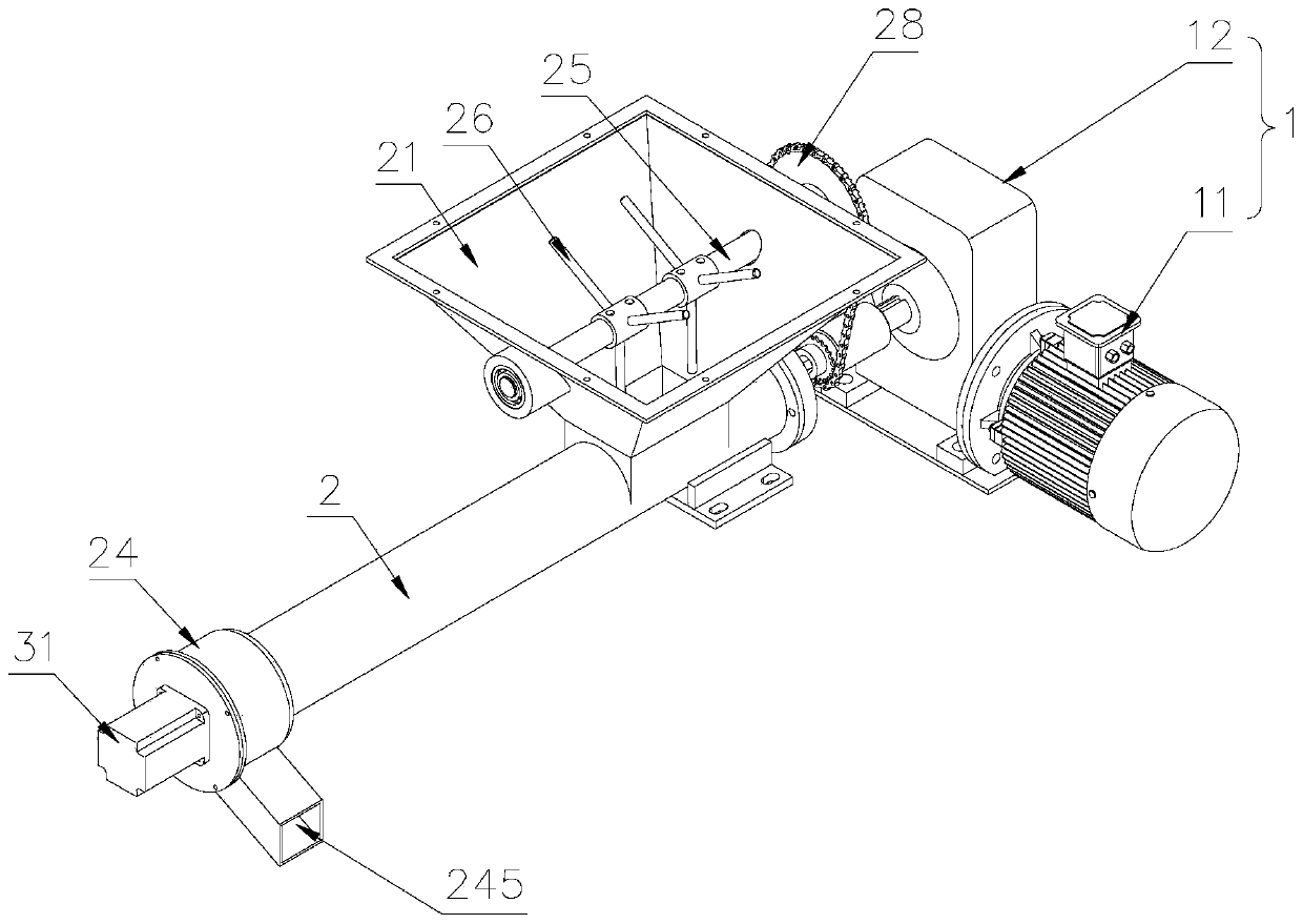
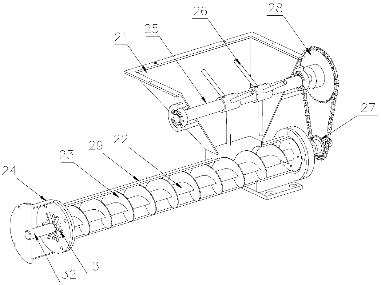
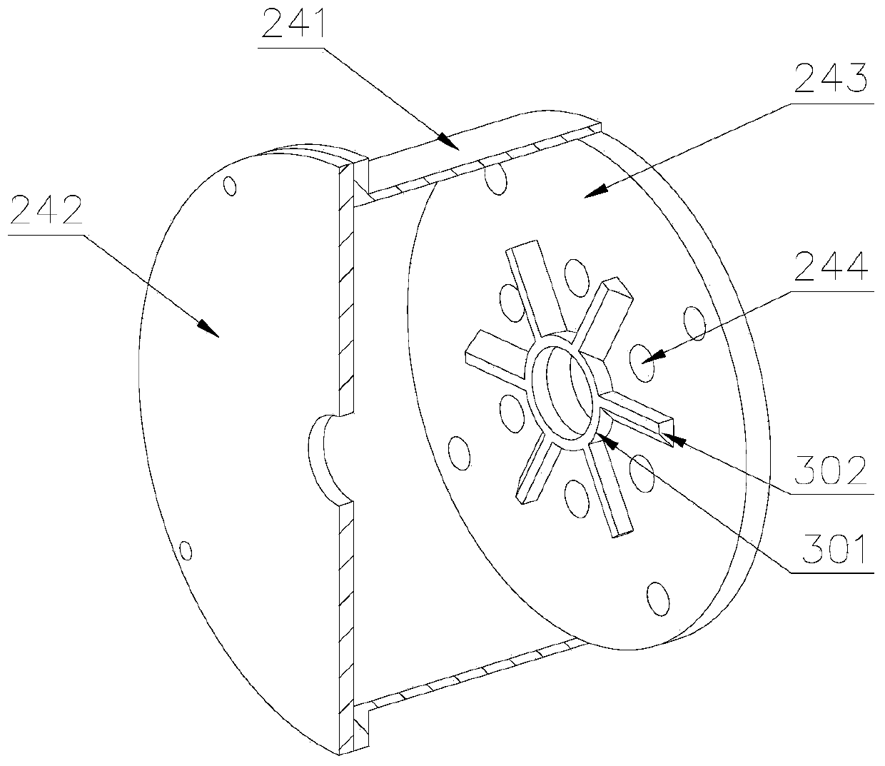
[0045] Such as Figure 1-3 As shown, a kind of elliptical ceramic particle granulator comprises a driving mechanism 1, an extruding mechanism 2, and a material cutting mechanism 3, and the driving mechanism 1 includes a driving motor 11, a speed reducer 12 connected to the driving motor 11 side, The extruding mechanism 2 includes a conveying cylinder 29, a feed hopper 21 arranged on the upper part of the conveying cylinder 29, a first rotating shaft 22 arranged inside the conveying cylinder 29, a helical blade 23 arranged outside the first rotating shaft 22, the first One end of a rotating shaft 22 is connected with the output shaft of the reducer 12 through a coupling; one end of the delivery cylinder 29 is connected with an extruding head 24, and an extruding plate 243 is arranged inside the extruding head 24, and on the extruding plate 243 Several extrusion holes 244 are provided, and the material cutting mechanism 3 is arranged at one end of the conveying cylinder 29 . Th...
Embodiment 2
[0050] Such as Figure 4 As shown, the difference from Embodiment 1 is that in this embodiment, the extrusion holes 244 are arranged in a straight line on the extrusion plate 243, and the material cutting mechanism 3 includes a U-shaped bracket 303 arranged on a U-shaped The ring-shaped squirrel-cage support 305 inside the bracket 303, and several cutters 302 evenly arranged outside the ring-shaped squirrel-cage support 305, every time the cutter shaft 32 rotates at a certain angle, the cutter 302 cuts off the blank at the same time, so as to ensure that each The length of the extruded ceramsite is equal; when the cutting knife 302 rotates to the center of the extrusion hole 244, the cutting knife 302 is in contact with the extruding plate 243, and the side of the U-shaped bracket 303 is provided with a second material cutting motor 304, and the second The output shaft of the material cutting motor 304 is connected with the ring-shaped squirrel-cage support 305, and the second...
Embodiment 3
[0052] Such as Figure 5-7 As shown, the difference from Embodiment 1 is that in this embodiment, the extrusion holes 244 are arranged in a straight line on the extrusion plate 243, and the material cutting mechanism 3 includes a base 306, which is arranged on both sides of the base 306 The vertical plate 307 of the vertical plate 307, the third cutting motor 308 arranged on one side of the vertical plate 307, the turntable 309 arranged between the vertical plates 307 on both sides, the turntable 309 is provided with two groups, and the turntable 309 side is connected to the vertical plate by the rotating shaft. The plate 307 is movably connected, the other side of the turntable 309 is connected with the output shaft of the third cutting motor 308, a connecting rod 311 is arranged between the two groups of turntables 309, and the connecting rod 311 is arranged eccentrically with the turntable 309, and one side of the base 306 is provided with There is a guide column 313, the g...
PUM
 Abstract
Description
Claims
Application Information
 - R&D
- Intellectual Property
- Life Sciences
- Materials
- Tech Scout
- Unparalleled Data Quality
- Higher Quality Content
- 60% Fewer Hallucinations
Browse by: Latest US Patents, China's latest patents, Technical Efficacy Thesaurus, Application Domain, Technology Topic, Popular Technical Reports.
© 2025 PatSnap. All rights reserved.Legal|Privacy policy|Modern Slavery Act Transparency Statement|Sitemap|About US| Contact US: help@patsnap.com