Axial-flow type high-flow-speed high-pressure-intensity test device
A test device, high flow rate technology, applied in the direction of measuring device, applying stable tension/pressure to test material strength, strength characteristics, etc., to achieve the effect of wide material sources, simple structure, and convenient operation and use
- Summary
- Abstract
- Description
- Claims
- Application Information
AI Technical Summary
Problems solved by technology
Method used
Image
Examples
Embodiment 1
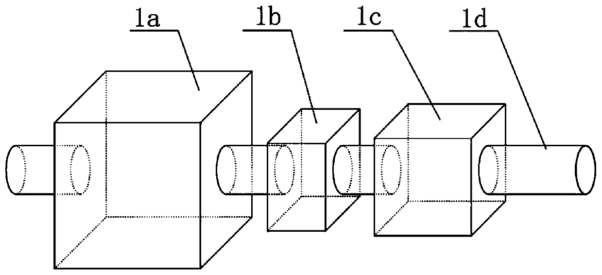
[0044] In the present embodiment a kind of axial-flow type high flow velocity high pressure test device, select the steel plate with 20mm thickness as the manufacturing material of container, and container is cuboid; The wall thickness of the tank is 5mm, and it is welded and fixed with the container; the fluid is seawater, and the sample is a metal sample.
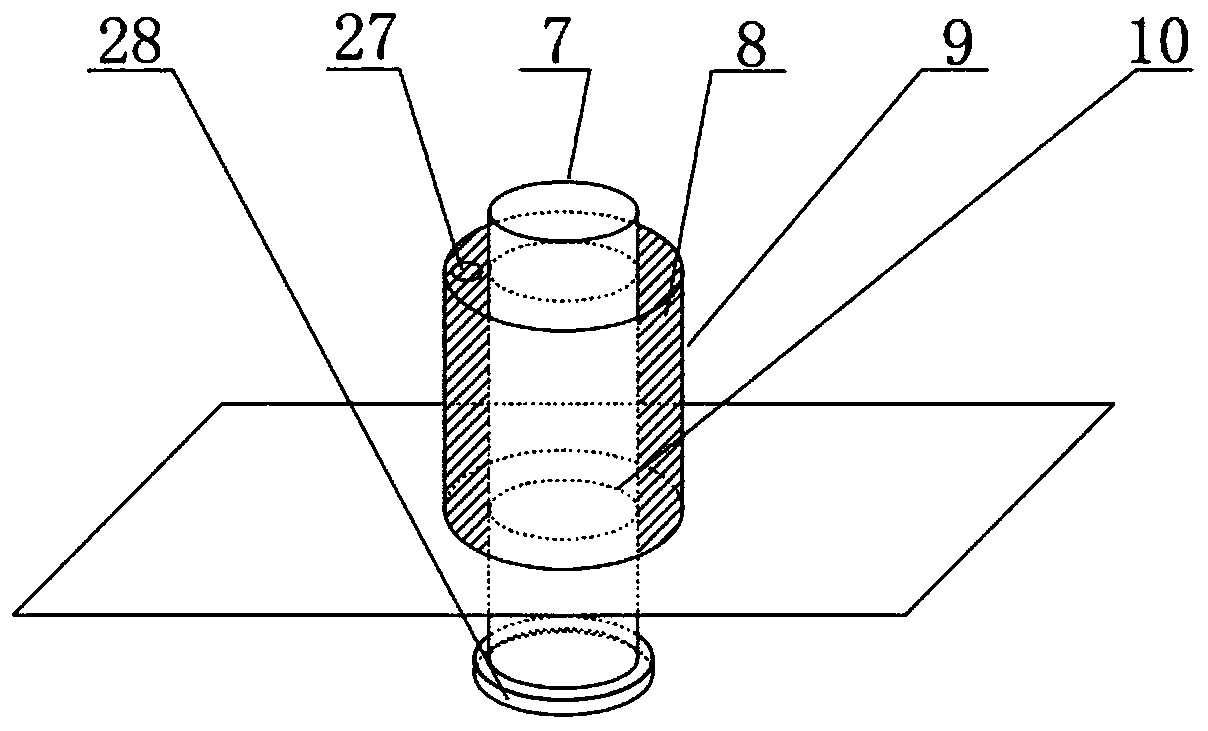
[0045] The fixed shaft and the movable shaft are respectively coupled and nested and run through the corresponding annular sleeves. The top of the fixed shaft is provided with an elastic fixing ring to prevent the sample from being displaced when it is impacted by high flow velocity; the movable shaft The bottom surface is pressed against the top surface of the sample.
[0046] The fluid inside the container should not be too full, it should be 30mm higher than the top surface of the sample. The fixed shaft and the movable shaft run through the two annular sleeves respectively. Grease to prevent air pressure leakage and ...
Embodiment 2
[0056] In this embodiment, the structure and composition of the axial-flow high-velocity high-pressure test device are basically the same as those in Embodiment 1. The container is a cube container, the fluid is lake water, and the sample is saturated rock.
[0057] In this embodiment, the axial-flow high-flow-velocity and high-pressure test device is inspected after assembly to ensure that each opening has a good seal, and the movable shaft and the annular sleeve are coupled and nested and have good mobility; ensure that Place the sample in the center of the container, keep the fixed shaft fixed; ensure that the butter in the annular sleeve 1 and annular sleeve 2 is sufficient and can isolate air and fluid; then start the test, adjust the compressed air delivery device, high pressure The fluid input device and the fluid output device keep the flow velocity and pressure of the sample in the container constant; the entire loading process of the sample is photographed through th...
Embodiment 3
[0059] In this embodiment, the structure and composition of the axial-flow high-velocity high-pressure test device are basically the same as those in Embodiment 1. The container is a cuboid container, the fluid is tap water that has been heated at 40°C, and the material sample is a columnar rock specimen.
[0060] In this embodiment, the axial-flow high-flow-velocity and high-pressure test device is inspected after assembly to ensure that each opening has a good seal, and the movable shaft and the annular sleeve are coupled and nested and have good mobility; ensure that Place the sample in the center of the container, keep the fixed shaft fixed; ensure that the butter in the annular sleeve 1 and annular sleeve 2 is sufficient and can isolate air and fluid; then start the test, adjust the compressed air delivery device, high pressure The fluid input device and the fluid output device keep the flow velocity and pressure of the sample in the container constant; the entire loading...
PUM
| Property | Measurement | Unit |
|---|---|---|
| diameter | aaaaa | aaaaa |
Abstract
Description
Claims
Application Information
 - R&D
- Intellectual Property
- Life Sciences
- Materials
- Tech Scout
- Unparalleled Data Quality
- Higher Quality Content
- 60% Fewer Hallucinations
Browse by: Latest US Patents, China's latest patents, Technical Efficacy Thesaurus, Application Domain, Technology Topic, Popular Technical Reports.
© 2025 PatSnap. All rights reserved.Legal|Privacy policy|Modern Slavery Act Transparency Statement|Sitemap|About US| Contact US: help@patsnap.com


