Fluoride red fluorescent powder and luminescent device based on fluorescent powder

A technology for red phosphors and light-emitting devices, applied in the directions of light-emitting materials, semiconductor devices, chemical instruments and methods, etc., can solve the problems of easy hydrolysis, low fluorescence quantum efficiency, and poor reliability, etc.

Inactive Publication Date: 2020-07-31
深圳市惠合显示有限公司
View PDF13 Cites 2 Cited by
  • Summary
  • Abstract
  • Description
  • Claims
  • Application Information

AI Technical Summary

Problems solved by technology

The main problems faced by phosphors in this system are: A x MF y :Mn 4+ The surface of phosphor particles is prone to hydrolysis, resulting in a decrease in quantum efficiency and poor reliability.
The disadvantage is that the crystallization interface is formed during the crystallization growth process of the shell layer, and there will be a large number of fluorescence quenching centers or light scattering centers at the crystallization interface, resulting in low fluorescence quantum efficiency; the outer surface of the shell layer has Mn 4+ Ions are prone to hydrolysis, resulting in a decrease in fluorescence quantum efficiency and poor reliability
Chinese patent CN103980896B adopts ion exchange method to synthesize A 2 MF 6 :Mn 4+ phosphors, the disadvantage is that the method relies on the transfer from the surface to a 2 MF 6 Mn inside the particle 4+ The concentration difference of ions is used as the driving force for ion exchange, and the phosphor particles finally produced have the highest Mn on the outer surface. 4+ Ion concentration, high concentration of Mn on the surface 4+ ions, causing it to be prone to hydrolysis, resulting in a decrease in fluorescence quantum efficiency and insufficient reliability

Method used


Image

  • Fluoride red fluorescent powder and luminescent device based on fluorescent powder
  • Fluoride red fluorescent powder and luminescent device based on fluorescent powder
  • Fluoride red fluorescent powder and luminescent device based on fluorescent powder

Examples


Embodiment 1

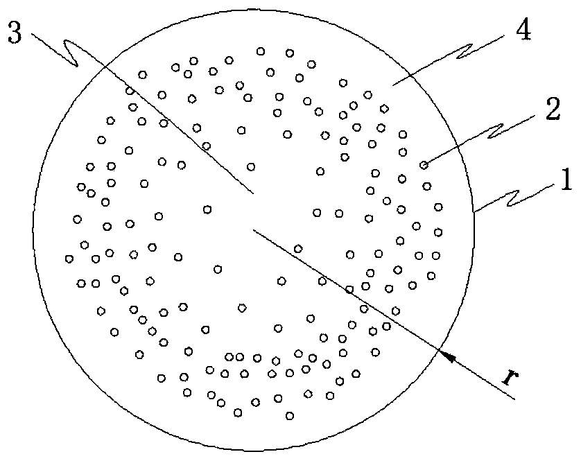
[0045] Please refer to Figure 1 to Figure 2 , A fluoride red phosphor, which is tetravalent manganese ion Mn 4+ Doped with K 2 TiF 6 As the luminescent ion in the matrix particles 1, K is potassium, F is fluorine, and the doped Mn 4+ Partially replace K 2 TiF 6 Tetravalent Ti in matrix particles 4+ Ion, the Mn 4+ Replace Ti 4+ The mole percentage of ions is Mn 4+ The incorporation concentration.

[0046] The K 2 TiF 6 There is a zero-incorporation zone 3 in the center of the matrix particle. The K 2 TiF 6 The matrix particles have a second zero-incorporation area close to the outer surface 4, Mn 4+ The doping concentration of ions 2 starts from the edge of the zero doping region 3 and continuously increases from zero to the maximum value, and then continuously decreases from the maximum value until it drops to zero at the edge of the second zero doping region 4.

[0047] The K 2 TiF 6 The matrix particle 1 is a matrix particle with a continuous lattice structure. 2 TiF 6 There is ...

Embodiment 2

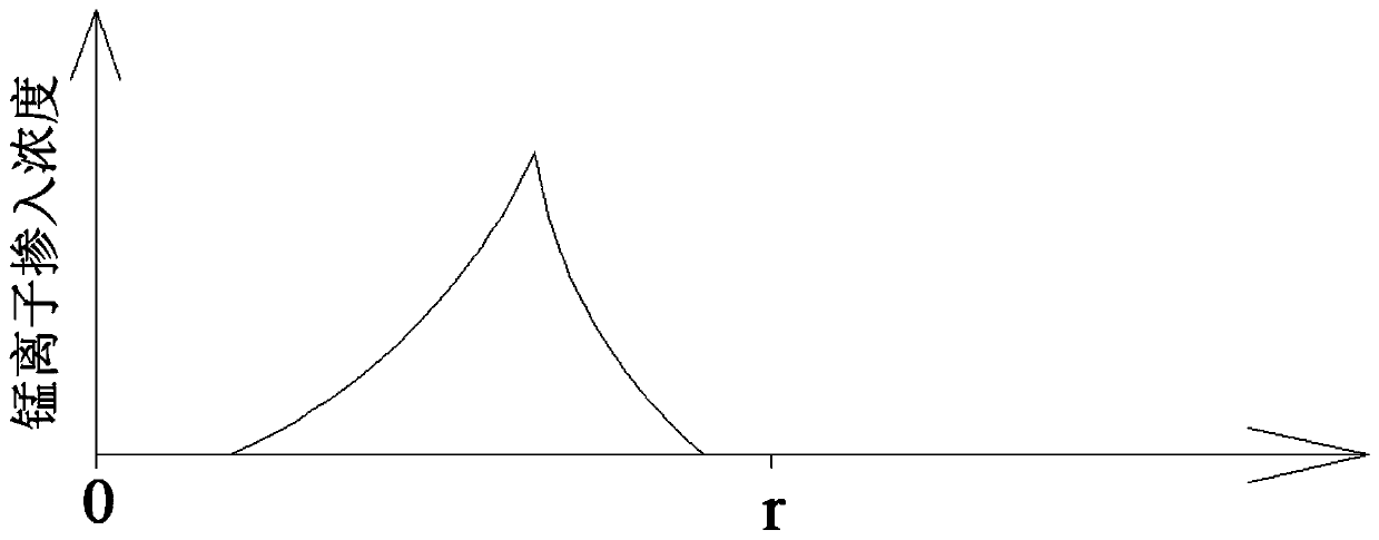
[0061] Please refer to image 3 Steps S106 and S107 in the first embodiment are omitted. In step S101, K 2 MnF 6 The concentration in the solution is 0.05 g / ml, and in step S102, the stirring time is 10 minutes. The K 2 TiF 6 There is a zero-incorporation zone 3 in the center of the matrix particle. Mn 4+ The doping concentration of ions is from the K 2 TiF 6 The center of the matrix particle first continuously increases from zero to the maximum value, and then continuously decreases from the maximum value until the K 2 TiF 6 The outer surface of the matrix particles is reduced to zero.

[0062] The K 2 TiF 6 The average particle size of the matrix particles is 9 microns. The K 2 TiF 6 The matrix particle 1 is a matrix particle with a continuous lattice structure. 2 TiF 6 There is no layered crystalline interface in any region from the center of the matrix particle 1 to the radial direction of its surface. 2 TiF 6 :Mn 4+ The peak wavelength of the red phosphor is around 631nm.

...

Embodiment 3

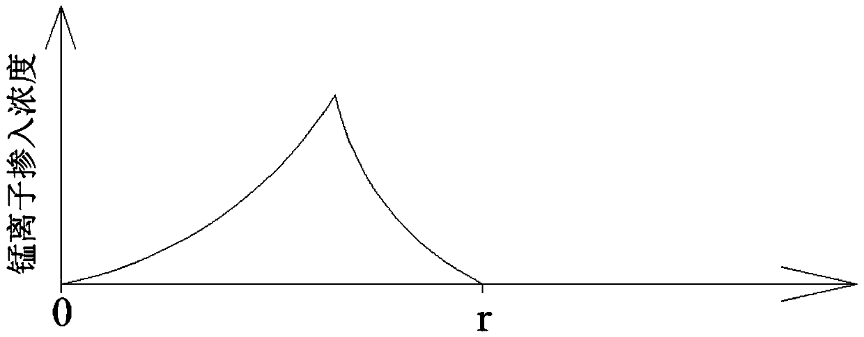
[0065] A fluoride red phosphor, which is tetravalent manganese ion Mn 4+ Incorporate K 2 SiF 6 The matrix particles act as luminescent ions.

[0066] K 2 SiF 6 The diameter of the matrix particles is 25 microns and the radius is 12.5 microns. 2 SiF 6 The total length in the radial direction from the center of the matrix particle to its surface is 12.5 microns, the position of the maximum incorporation concentration is 8.75 microns in the radial direction from the center of the matrix particle to its surface, and the outer edge of the zero incorporation region The position is 2.5 micrometers in the radial direction from the center of the matrix particle to its surface, and the thickness of the second zero-incorporation region is 1.25 micrometers.

[0067] Preparation of the K 2 SiF 6 :Mn 4+ In the method of fluoride red phosphor,

[0068] In the S101 step, K 2 MnF 6 The concentration in the solution is 0.06g / ml;

[0069] In the step S102, at 25°C, the K with an average particle diamete...


PUM

PropertyMeasurementUnit
particle sizeaaaaaaaaaa

Abstract

The invention relates to a fluoride red fluorescent powder and a luminescent device based on the fluorescent powder. According to the fluoride red fluorescent powder, tetravalent manganese ions Mn < 4+ > are doped into K2MF6 matrix particles to serve as light-emitting ions; wherein from the radial direction from the centers of the K2MF6 matrix particles to the surfaces of the K2MF6 matrix particles, the doping concentration of Mn < 4 + > is controlled to continuously increase from zero to the maximum value, and then reduce from the maximum value to zero; the K2MF6 matrix particles are matrixparticles with continuous lattice structures; no layered crystallization interface exists in the radial direction from the centers of the K2MF6 matrix particles to the surfaces of the K2MF6 matrix particles. In the luminescent device, the K2MF6: Mn < 4 + > red fluorescent powder is arranged on a light emitting path of an LED chip, and the K2MF6: Mn < 4 + > red fluorescent powder is arranged between an upper layer transparent optical medium and a lower layer transparent optical medium.

Description

Technical field [0001] The present invention relates to the field of optoelectronics, in particular to a fluoride red phosphor and a light emitting device based on the phosphor. Background technique [0002] The mature development of blue LED technology based on the third-generation semiconductor GaN has greatly promoted the application of LEDs in lighting and display fields. LED lighting has many advantages such as higher light efficiency, more environmental protection, simpler drive, and good compatibility with Internet of Things control, and has formed a comprehensive replacement of traditional lighting technology. In the display field, LED backlights have become a commonly used backlight technology in the liquid crystal display industry; new display technologies such as MiniLED displays and MicroLED displays based on LED chips are also emerging in endlessly. [0003] For LED lighting products used in general lighting, the spectrum must be a continuous spectrum covering the ent...

Claims


Application Information

Patent Timeline
Patent Type & Authority Applications(China)
IPC IPC(8): C09K11/61C09K11/67H01L33/50
CPCC09K11/617C09K11/674H01L33/502
Inventor 郭伟杰
Owner 深圳市惠合显示有限公司
Why Eureka
Try Eureka