
Swirling burner for pulverized coal dense and thin separation of lignite

A swirl burner and concentration separation technology, applied in the burners, burners, combustion methods and other directions of burning powder fuel, can solve the problems affecting the flow field and combustion process of the burner, the poor stability of the flame recirculation zone, the secondary air rate Small and other problems, to achieve the effect of stable flow field, small unburned heat loss, and reduction of air volume and momentum

Pending Publication Date: 2020-07-24
HARBIN BOILER
View PDF11 Cites 14 Cited by
  • Summary
  • Abstract
  • Description
  • Claims
  • Application Information

AI Technical Summary

Problems solved by technology

[0005] The present invention solves the problem that the primary air-to-coal ratio and the primary air rate of the existing swirl burner are relatively large, and the secondary air rate is relatively small, resulting in a large difference in the momentum ratio between the primary air and the secondary air, which affects the flow rate of the burner. The field and combustion process are not easy to control, and the stability of the flame recirculation zone is poor, resulting in high NO x To solve the problem of pollutants, and provide a swirl burner suitable for the separation of thick and thin coal pulverized coal of lignite

Method used


Image

  • Swirling burner for pulverized coal dense and thin separation of lignite
  • Swirling burner for pulverized coal dense and thin separation of lignite
  • Swirling burner for pulverized coal dense and thin separation of lignite

Examples


Embodiment 1

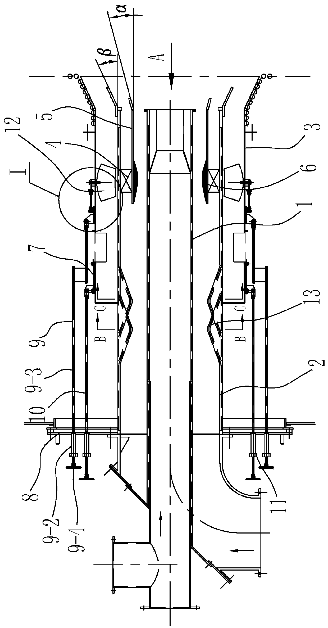
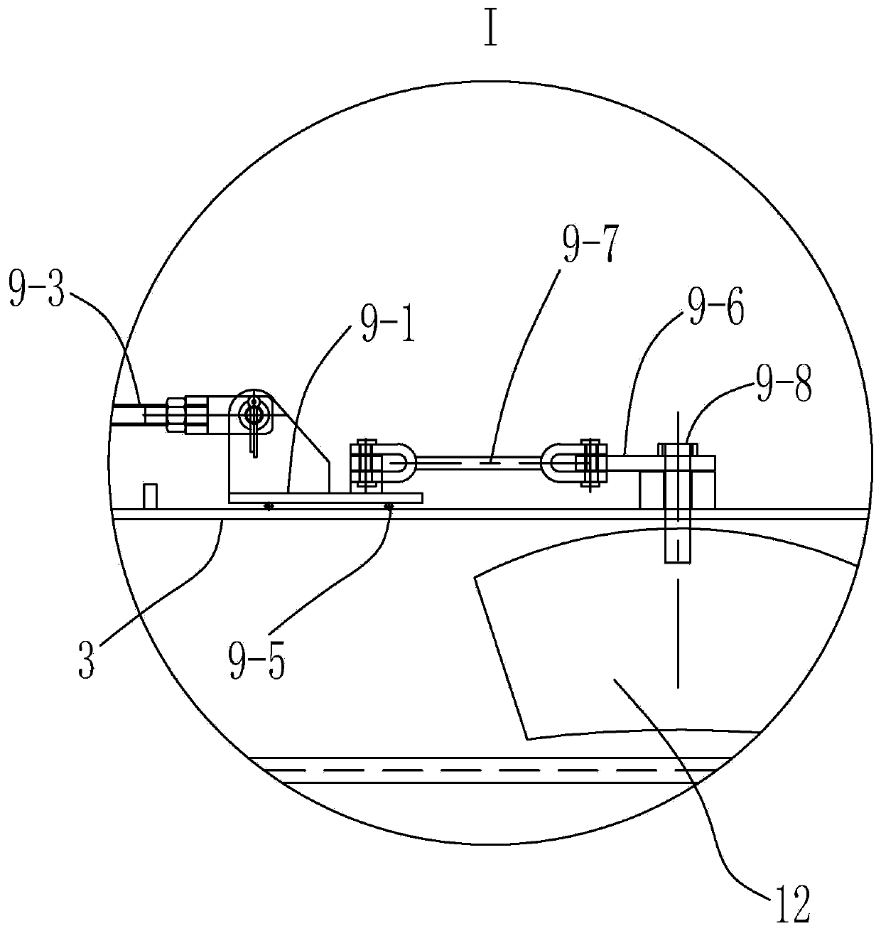
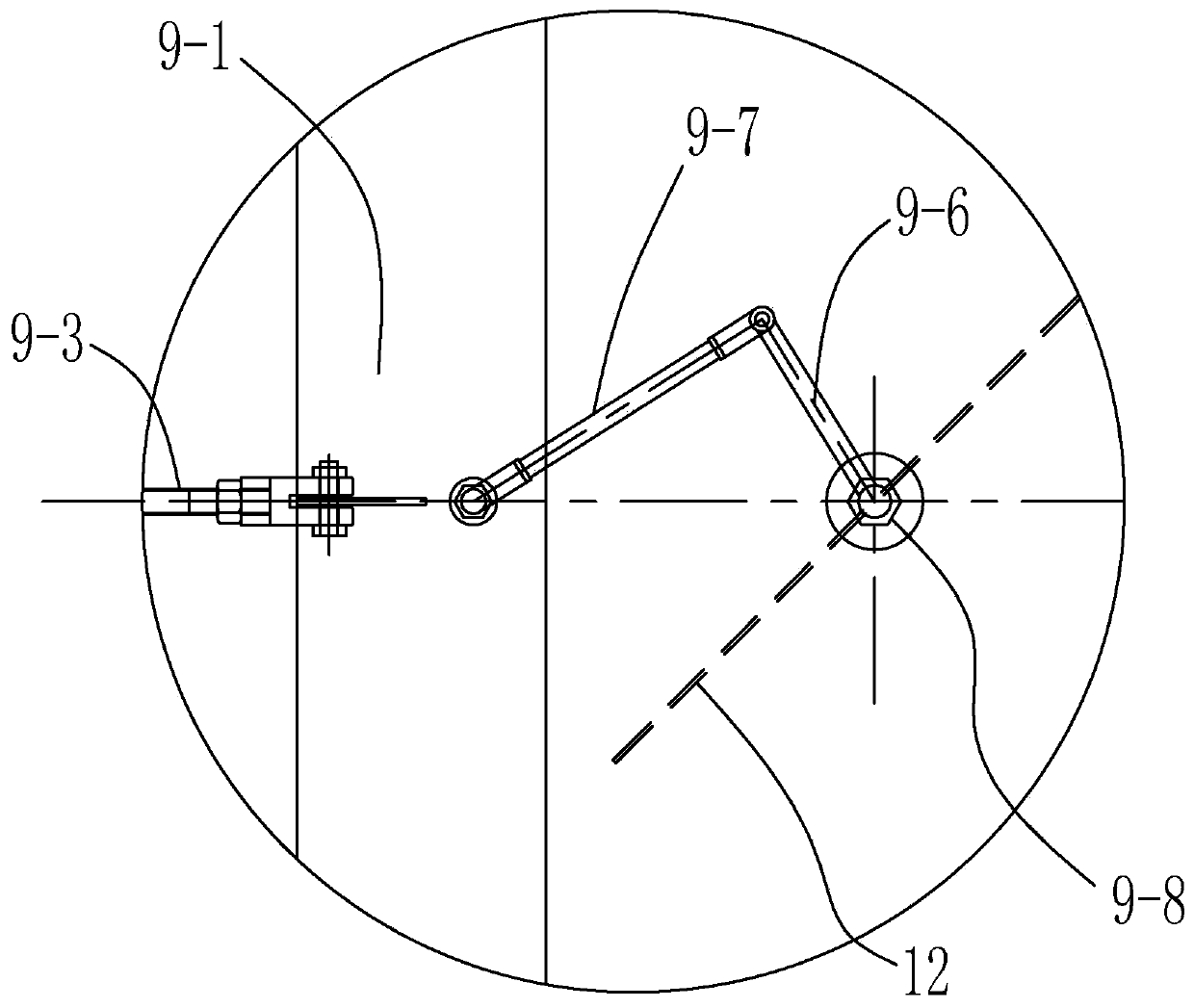
[0021] Embodiment 1: as figure 1 As shown, the present embodiment relates to a swirl burner suitable for separation of pulverized coal concentration and thinness of lignite, central air duct 1, primary air duct 2, secondary air duct 3, secondary air swirl blades 12 and Venturi coal Powder concentrating pipe 6 is characterized in that it also includes dilute phase swirl blade 4, thick-lean separation cylinder 5, pulverized coal concentration separation device 13, central air duct 1, thick-lean separation cylinder 5, primary air duct 2 and secondary The air ducts 3 are set together from the inside to the outside, and the adjacent two are arranged at intervals. There are a plurality of light-phase swirls evenly distributed along the circumferential direction of the primary air duct 2 between the thick-thin separation compartment 5 and the primary air duct 2. Blades 4, between the primary air duct 2 and the secondary air duct 3 are provided with a plurality of secondary air swirl...


PUM


Abstract

The invention relates to a swirling burner for pulverized coal dense and thin separation of lignite, belongs to the technical field of a boiler burner, and aims to solve the problem that the coal-airratio of primary air and the primary air ratio of the existing swirling burner for burning lignite are larger, and the secondary air ratio is smaller, so that the momentum ratio of primary air and secondary air is much different from that of burning bituminous coal, and the flow field and the burning process control of the burner are affected; and thus, the burning process of the burner is not easy to control, the stability of a flame backflow zone is poor, and higher NOx pollutants are produced. The swirling burner for pulverized coal dense and thin separation of lignite comprises a central air pipe, a primary air pipe, a secondary air pipe, a secondary air swirl vane, a venturi pulverized coal concentration pipe, thin-phase swirl vanes, a dense and thin separation isolating barrel and apulverized coal dense and thin separation device, wherein the central air pipe, the dense and thin separation isolating barrel, the primary air pipe and the secondary air pipe are arranged together from inside to outside in a sleeved mode, and every two adjacent components are arranged at intervals; and a plurality of thin-phase swirl vanes which are uniformly distributed on the peripheral direction of the primary air pipe are arranged between the dense and thin separation isolating barrel and the primary air pipe.

Description

technical field [0001] The invention relates to a boiler burner, in particular to a swirl burner for lignite, and belongs to the technical field of boiler burners. Background technique [0002] The swirl burner is a type of burner that mixes the primary air carrying pulverized coal with the combustion air (secondary air) and sprays it into the boiler furnace in the form of swirl to organize combustion. [0003] Due to the various types of coal, the physical and chemical properties of various types of coal are quite different, and the structure of the burner needs to be designed according to the difference in coal quality. [0004] At present, most swirl burners are developed on the basis of bituminous coal, and are mainly suitable for bituminous coal, and are equipped with internal secondary air. Compared with the bituminous coal burner, the lignite burner has a larger primary air-to-coal ratio and primary air rate, and the embers are separated from the total secondary air,...

Claims


Application Information

Patent Timeline
IPC IPC(8): F23D1/02F23L9/00
CPCF23D1/02F23L9/00
Inventor 韩升利王通黄莺王静杰徐彦辉祝令昆
Owner HARBIN BOILER
Learn More