Coplanar wireless power transmission system for enhancing mutual inductance by applying soft magnet

A wireless power transmission, soft magnetic technology, applied in the direction of preventing/reducing unwanted electrical/magnetic effects, circuits, inductors, etc. System design, the effect of expanding application prospects

Pending Publication Date: 2020-07-17
NANCHANG UNIV
View PDF3 Cites 0 Cited by
  • Summary
  • Abstract
  • Description
  • Claims
  • Application Information

AI Technical Summary

Problems solved by technology

[0007] The purpose of the present invention is to solve the problem of low system efficiency caused by the low coupling coefficient of adjacent coils in the coplanar wireless power transfer (WPT) system in the prior art, and proposes a soft magnetic material with a low profile to enhance Coplanar WPT system with mutual inductance of adjacent coils

Method used


Image

  • Coplanar wireless power transmission system for enhancing mutual inductance by applying soft magnet
  • Coplanar wireless power transmission system for enhancing mutual inductance by applying soft magnet
  • Coplanar wireless power transmission system for enhancing mutual inductance by applying soft magnet

Examples


Embodiment 1

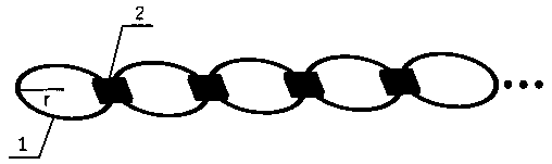
[0043] Example 1. Coplanar single-transmission-single-relay-single-reception wireless power transfer system.

[0044] The system as Figure 11 As shown, the system consists of 3 coils and 4 pieces of ferrite. The diameter of each enamelled copper wire coil is 1mm, the radius r=100mm, the number of turns n=10, and the internal resistance of the coil is 0.5Ω. The resonant frequency is set to 100kHz. Below 1 MHz, Mn-Zn ferrite has excellent properties in terms of material effect and loss. Select 4 pieces of PC40 ferrite with a length, width and height of 70mm×75mm×5mm (magnetic permeability μ=2300±25%, the condition is 100kHz, 200mT, 25℃, power consumption P v =600mW / m 3 ), using a double-layer structure. The entire system including the power supply V S , the source coupled coil L 1 , source tuning capacitor C 1 , relay coupling coil L 2 , relay tuning capacitor C 2 , the load-side coupling coil L 3 , the load-side tuning capacitor C 3 , R is a simplified external loa...

Embodiment 2

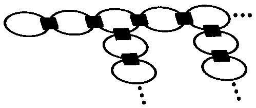
[0048] Example 2. Tree.

[0049] Figure 14 As an example of the tree structure WPT in this embodiment, a two-layer structure is adopted. The structure consists of 7 coils of enamelled copper wire and 12 pieces of Mn-Zn ferrite (PC40). The wire diameter of the coil is 1mm, the radius is 100mm, and the number of turns is 10 turns. The resonant frequency of the system is 100kHz. When no soft magnet is added, the inductance L 1 =46.82μH, tuning capacitor C 1 =50.30nF, inductance L 2 =46.62μH, tuning capacitor C 2 =54.39nF, inductance L 3 =46.92μH, tuning capacitor C 3 =53.99nF, inductance L 4 =46.5μH, tuning capacitor C 4 =54.5nF, inductance L 5 =47μH, tuning capacitor C 5 =53.9nF, inductance L 6 =46.8μH, tuning capacitor C 6 =54.17nF, inductance L 7 =46.8μH, tuning capacitor C 7 =54.17nF. The quality factor of each coil is Q 1 =58.83,Q 2 =58.58,Q 3 =58.96,Q 4 =58.43,Q 5 =59.06,Q 6 =58.81,Q 7 =58.81. The coupling coefficient of the adjacent coil is 0.043...


PUM

PropertyMeasurementUnit
inductanceaaaaaaaaaa

Abstract

The invention discloses a coplanar wireless power transmission system for enhancing mutual inductance by applying a soft magnet. The coplanar wireless power transmission systemstructure is characterized in that the structure comprisesby comprising an inversion alternating current power supply, one or more receiving ends, a plurality of LC resonators and a plurality of groups of soft magnet structures., the The LC resonators are connected through the soft magnets, the inversion alternating current power supply is connected to the first LC resonator, the receiving end is connected to the last LCresonator, and a chain-shaped or tree-shaped coplanar structure is formed. The structural section is small; according to the utility model, the coplane can be realized, the mutual inductance betweenadjacent coils is enhanced, the transmission efficiency is greatly improved, and the cross mutual inductance between non-adjacent coils is effectively inhibited and is generally 1-2 orders of magnitudes smaller than that of main coupling, so that the electric energy multipath transmission caused by cross coupling in the system can be ignored , and the design difficulty is reduced.

Description

technical field [0001] The invention belongs to the technical field of wireless energy transmission system design. Background technique [0002] Among various wireless power transfer (WPT) technologies, magnetically coupled resonant wireless charging (MCR-WPT) is an efficient mid-range wireless charging technology, and in the research and application of MCR-WPT, a large number of them are Coaxial WPT system. The coplanar wireless power transmission system uses planar coils, and the coils are placed along the floors, ceilings, desktops, walls and other surfaces, which can effectively save space and overcome the disadvantages of coaxial WPT systems that occupy space and are not beautiful. However, the mutual inductance of adjacent planar coils placed on the same plane is often small, resulting in small inductive coupling and low system transmission efficiency, thus limiting the application of coplanar WPT systems. [0003] Patent CN110085393A proposes a π-type ferrite and pl...

Claims


Application Information

Patent Timeline
Patent Type & Authority Applications(China)
IPC IPC(8): H02J50/12H01F38/14H01F27/38
CPCH01F27/38H01F38/14H02J50/12
Inventor 罗斌左洋卓康韩旺君马东亚曾金辉朱启标
Owner NANCHANG UNIV
Why Eureka
Try Eureka