
Power plant wastewater evaporation crystallizer

A technology for evaporating crystallizer and power plant wastewater, which is applied in gaseous effluent wastewater treatment, chemical instruments and methods, heating water/sewage treatment, etc. path and other issues to prevent blockages

Pending Publication Date: 2020-07-10
GUODIAN ENVIRONMENTAL PROTECTION RES INST CO LTD +1
View PDF1 Cites 1 Cited by
  • Summary
  • Abstract
  • Description
  • Claims
  • Application Information

AI Technical Summary

Problems solved by technology

[0004] However, when using this high-efficiency and energy-saving wastewater evaporation crystallizer, the flue gas is directly introduced into the main body of the evaporation tube through the inlet of the evaporation tube. There is a large amount of dust in the flue gas, and the dust will adhere to the inner wall of the main body of the evaporation tube and waste water. Too much dust adheres to the outer wall of the nozzle and the inner wall of the main body of the evaporation tube, which will reduce the flow and velocity of the flue gas, thereby reducing the evaporation efficiency of the waste water droplets. In addition, a large amount of dust piled up on the outer wall of the waste water nozzle will cause Blocking the spraying path of the wastewater nozzle and reducing the spraying area will reduce the effect of atomization, so it needs to be shut down and disassembled to clean up the dust, which will waste a lot of manpower and time. In addition, the high-temperature flue gas will evaporate the high-efficiency and energy-saving wastewater. The temperature of the crystallizer is high, and it is necessary to wait for the high-efficiency energy-saving wastewater evaporation crystallizer to cool down before cleaning, which will also consume time and greatly reduce the utilization rate of the equipment

Method used


Image

  • Power plant wastewater evaporation crystallizer
  • Power plant wastewater evaporation crystallizer
  • Power plant wastewater evaporation crystallizer

Examples


Embodiment

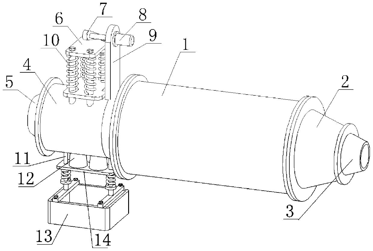
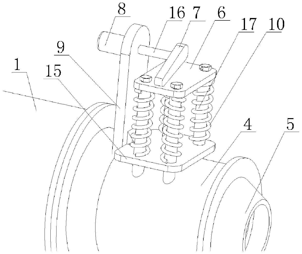
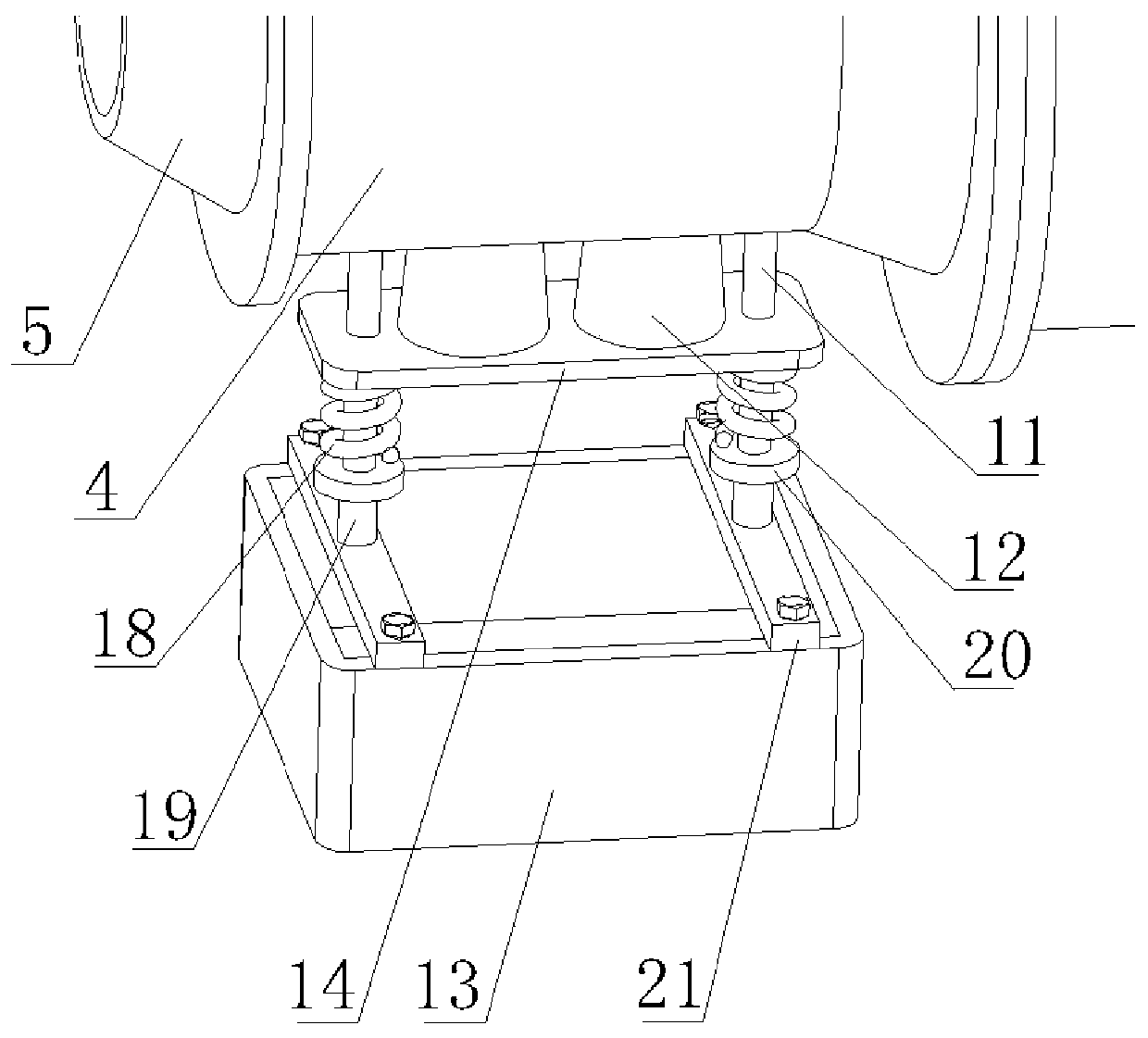
[0034] Such as figure 1 As shown, a power plant wastewater evaporation crystallizer in this embodiment includes an evaporation tube inlet 5, a horizontal section 4, an evaporation tube main body 1, an outlet chamber 2, and an evaporation tube outlet 3 connected in sequence, and the evaporation tube inlet 5 and the horizontal section 4 Through the flange sealing connection, the horizontal section 4 is connected to the evaporation tube main body 1, the gas outlet end of the evaporation tube main body 1 is connected to the outlet chamber 2, the outlet chamber 2 is connected to the evaporation tube outlet 3 through a flange sealing connection, and the inner wall of the horizontal section 4 is fixed A filter screen 25 is installed, and the top and the bottom are respectively provided with a first through hole and a second through hole. In this embodiment, there are four first through holes and two second through holes.

[0035] combine figure 2 As shown, the top of the horizontal...


PUM


Abstract

The invention discloses a power plant wastewater evaporation crystallizer which comprises an evaporation pipe inlet, a horizontal section, an evaporation pipe main body, an outlet chamber and an evaporation pipe outlet which are sequentially communicated. The evaporation pipe inlet is hermetically connected with the horizontal section through a flange, the horizontal section is connected with theevaporation pipe main body, and the gas outlet end of the evaporation pipe main body is connected with the outlet chamber. The power plant wastewater evaporation crystallizer is simple in structure, adriving motor, a cam, a first spring, a sliding rod, a top plate, a second spring, a guide column and other structures are matched, the steel wire brush can do longitudinal reciprocating motion on the filter screen, the conical column can do longitudinal reciprocating motion, smoke dust can be effectively prevented from adhering to the inner wall of the evaporation pipe main body and the outer wall of the wastewater spray head, the atomizing effect of the nozzle is prevented from being reduced, the possibility that the outlet of the evaporator is blocked is reduced, dust on the filter screencan be removed without disassembling and cooling the equipment, a large amount of manpower and time are saved, the utilization rate of the equipment is increased and the equipment is convenient to use.

Description

technical field [0001] The invention relates to power plant wastewater treatment equipment, in particular to a novel power plant wastewater evaporation crystallizer, which belongs to the field of power plant pollutant discharge reduction. Background technique [0002] my country is a country dominated by thermal power generation. The burning of coal in thermal power plants causes serious air pollution. The power generation system SO 2 Emissions accounted for the national SO 2 more than 45% of emissions. In response to State's response to SO 2 Most of the thermal power plants are equipped with desulfurization systems. Limestone-gypsum wet flue gas desulfurization technology has become the first choice due to its advantages such as high desulfurization efficiency, stable equipment operation, cheap absorbent raw materials, and reusable by-products. The first choice for thermal power plant desulfurization process. However, the system will generate a certain amount of desulfu...

Claims


Application Information

Patent Timeline
Patent Type & Authority Applications(China)
IPC IPC(8): B01D46/10B01D46/00B01D46/48C02F1/04C02F103/18
CPCB01D46/10B01D46/48C02F1/04C02F2103/18B01D46/681
Inventor 佘晓利周香韦飞吴韶飞王梦琴王特孙尊强申智勇刘志坦
Owner GUODIAN ENVIRONMENTAL PROTECTION RES INST CO LTD
Learn More